Concept illustration
Read diagram notes
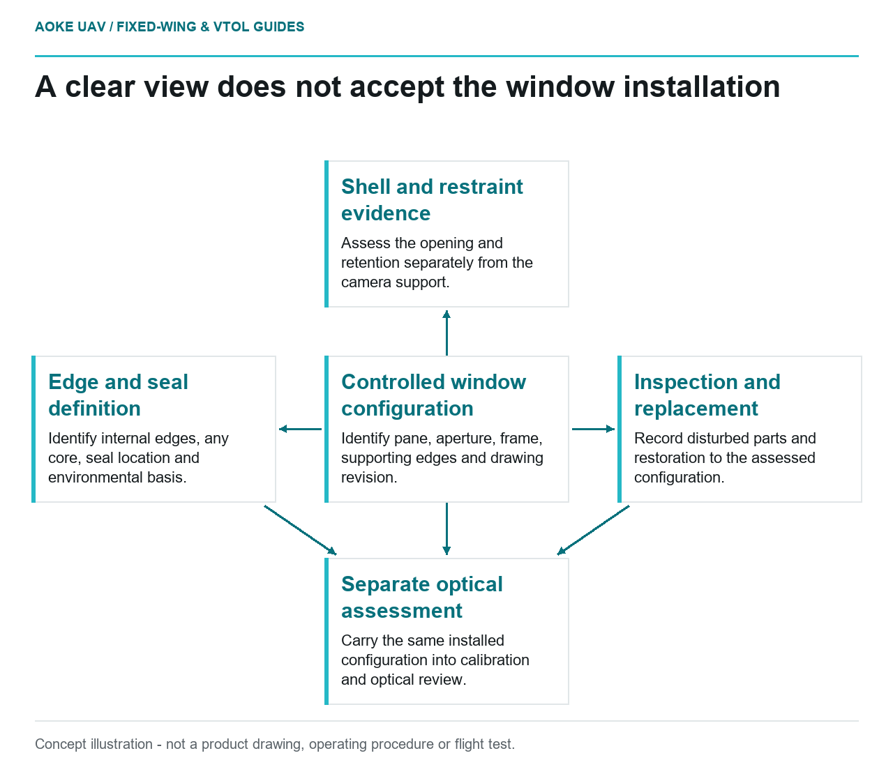
- Controlled window configuration: Identify pane, aperture, frame, supporting edges and drawing revision.
- Shell and restraint evidence: Assess the opening and retention separately from the camera support.
- Edge and seal definition: Identify internal edges, any core, seal location and environmental basis.
- Inspection and replacement: Record disturbed parts and restoration to the assessed configuration.
- Separate optical assessment: Carry the same installed configuration into calibration and optical review.
A hypothetical large fixed-wing mapping aircraft needs a window below its camera bay. The optical supplier confirms that the proposed pane can provide the desired view, but that does not resolve the fuselage opening or attachment. This review concerns the shell, restraint, edge construction and maintenance interface. Optical calibration through the installed window is a related but separate question. No aperture dimensions, pane thickness, mounting loads or sealant specification can be established without the actual aircraft and window design documentation.
Aperture interrupting the shell load path
Ask the airframe authority to identify the existing shell construction and the proposed opening in a controlled drawing. Request the evidence connecting that aperture and any surrounding features to the assessed structure. A drawing should distinguish the opening itself from a removable external fairing or camera support; combining them under the word window can obscure which interface is being reviewed.
FAA guidance treats cut-outs, joints and other discontinuities as matters for configuration-specific structural substantiation within a building-block approach. [1] Its scope is US certificated aircraft and does not approve a hole in this fixed-wing UAV. The practical question is whether the proposed aperture is represented in applicable evidence. Do not infer acceptance from the camera’s field of view or from another aircraft having a similarly shaped opening.
Window restraint and edge support
Request the defined restraint arrangement, supporting edges and relationship between pane, frame and fuselage. Ask which installed configuration was assessed, including any removable retainers and supporting components. Keep the camera support definition separate unless the design explicitly combines the functions. This is a review request, not a proposed window mounting scheme.
For this industrial fixed-wing integration, ask how the designer reconciles the required view with the structural attachment. If a retainer interferes with the optical path, neither trimming it nor enlarging the aperture follows automatically. FAA structural-detail guidance emphasizes specific design features and relevant substantiation. [1] Use that principle to return the conflict to the responsible designers. Optical acceptability and mechanical retention need linked configurations but different evidence; one cannot silently approve the other.
Sealing without hidden core exposure
Ask for a section identifying the opening edge, any sandwich core, seal location and inspection access. Request the applicable environmental assumptions and the evidence for the completed interface. A seal on the visible outer perimeter does not, by description alone, identify the protection of every internal edge. Do not prescribe extra potting or sealant as an improvised improvement.
NASA JSC’s sandwich assembly specification ties core preparation and insert-related potting to drawings and controlled process instructions. It is a NASA process example, not an aircraft window standard. [2] FAA guidance also addresses environmental protection and moisture exposure for composite structure. [1] Together they frame a supplier question about the actual construction; they do not supply a transferable sealing recipe or establish weather qualification for this fixed-wing aircraft.
Inspection and replacement access
Ask how the window is removed, replaced and inspected under the applicable maintenance documents. Determine which parts are disturbed during replacement and which records are required afterward. The review should identify how a replacement pane and retention configuration remain associated with the relevant drawing revision. Avoid assuming a replacement of similar appearance is equivalent.
FAA maintenance guidance emphasizes access and part-specific procedures and records, including the limitations of visual indications for hidden damage. [1] For the hypothetical large fixed-wing program, close the structural review with the aperture disposition, retention evidence, edge/seal definition and maintenance route. Then carry that exact installed configuration into any optical assessment. A clear view through the pane remains an optical observation; it is not evidence that the modified shell, supporting edges or window restraint have received structural acceptance.