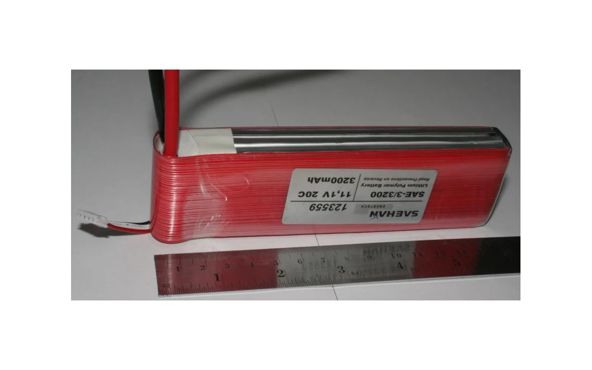
A hypothetical large civil fixed-wing VTOL is being considered for corridor mapping. Its battery proposal relies on a discharge label. Before treating that label as a design input, distinguish three statements: a capacity-normalized current, a manufacturer’s cell test under specified conditions, and an installed pack’s capability. They are not interchangeable. The example below interprets published evidence; it recommends neither this cell nor an aircraft current.
Rating definition and test method
Tenergy’s battery glossary defines C-rate as charge or discharge current expressed relative to rated capacity. Its capacity definition also requires specified discharge conditions. Thus a C-number needs an identified ampere-hour reference, not merely a prominent multiplier. The glossary distinguishes constant-current discharge from constant-power discharge, in which current increases as voltage decreases. A test’s load regime therefore matters alongside its C-number.[1]
For a descriptive manufacturer example, Molicel’s INR-21700-P42A datasheet, version 1.7, lists typical capacity of 4200 mAh and minimum capacity of 4000 mAh, and includes a 20 A discharge curve. Normalizing that plotted current gives 20/4.2 = approximately 4.76C using typical capacity, but 20/4.0 = 5C using minimum capacity. These are calculated descriptions of the same cell example, not two different tested currents or aircraft recommendations.[2]
Duration and temperature rise
The P42A discharge-rate chart specifies 23°C and termination at 2.5 V, with stated charge preconditioning. It describes discharge to an endpoint, not a fixed number of burst seconds. Separately, its cycle chart specifies constant-current discharge, 23°C, the same voltage endpoint, and a 30-minute rest after the 20 A discharge. That rest belongs to that laboratory cycle sequence; it is not a permitted flight pulse or a repeat-burst allowance.[2]
The datasheet lists 45 A as continuous discharge current, but the discharge-rate plot’s highest labeled curve is 30 A. Do not present that plot as a measured 45 A temperature-rise qualification.[2] Temperature conditions and temperature rise are different evidence: a stated test temperature does not itself reveal how hot the cell became. For the hypothetical fixed-wing VTOL, a lift interval followed by cruise and another lift interval also differs from a discharge followed by the documented laboratory rest. Missing thermal traces or duty-profile correspondence cannot be repaired by relabeling the curve.
Cell evidence versus finished-pack evidence
Consider two hypothetical proposals citing that same cell document. One provides only the cell sheet; the other also identifies its finished enclosure, interconnects, output connector and protection architecture. Neither proposal becomes accepted merely by naming more hardware. The second, however, exposes the additional interfaces whose capability and protection behavior must support the assembled claim.
Suppose the offered protection system interrupts output before the cell-sheet current is reached. A multiplication based only on cell capacity would miss that conditional behavior. Conversely, absence of interruption would not demonstrate acceptable temperatures throughout an enclosure. These are alternative review cases, not observed results. FAA AC 20-184A reinforces the system boundary by calling for evaluation of lithium-battery impedance characteristics with other aircraft electrical components. It is aircraft certification guidance, not the source of a commercial C-rating or approval for this UAV.[3]
Evidence for the actual installed pack
The useful supplier question is now specific: which offered-pack evidence supports the proposed load regime, endpoint, thermal environment and repetition pattern, including protection and output interfaces? A supported answer would identify the tested pack revision and reconcile those conditions with the proposed installation. An unsupported answer would repeat the cell’s continuous-current row while omitting the assembled current path and test boundary.
For the large fixed-wing project, retain the cell example as an interpretation aid, not an acceptance value. Molicel itself describes its sheet as reference information rather than a performance guarantee.[2] This review concerns the meaning and substantiation of discharge labels; installed usable energy remains a separate question. No charging procedure, pack selection or safe operating current follows from this illustration.
Related reading
Sources
- [1] Battery Glossary
- [2] PRODUCT DATA SHEET MODEL INR-21700-P42A
- [3] Guidance on Testing and Installation of Rechargeable Lithium Battery and Battery Systems on Aircraft, AC 20-184A
Visual summary
Concept illustration
Read diagram notes
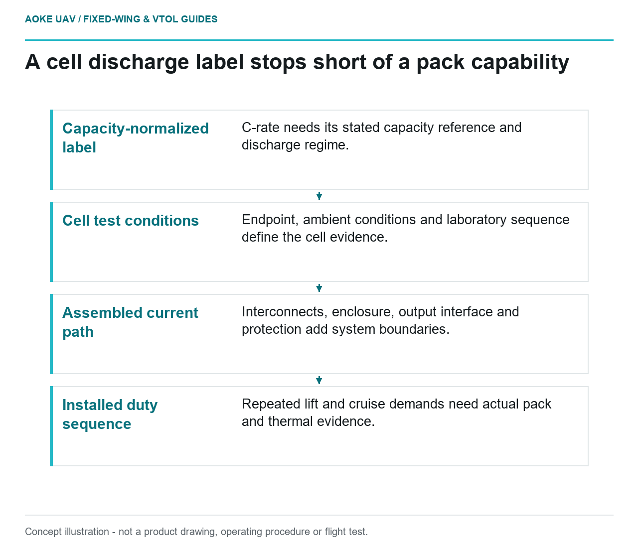
- Capacity-normalized label: C-rate needs its stated capacity reference and discharge regime.
- Cell test conditions: Endpoint, ambient conditions and laboratory sequence define the cell evidence.
- Assembled current path: Interconnects, enclosure, output interface and protection add system boundaries.
- Installed duty sequence: Repeated lift and cruise demands need actual pack and thermal evidence.