Concept illustration
Read diagram notes
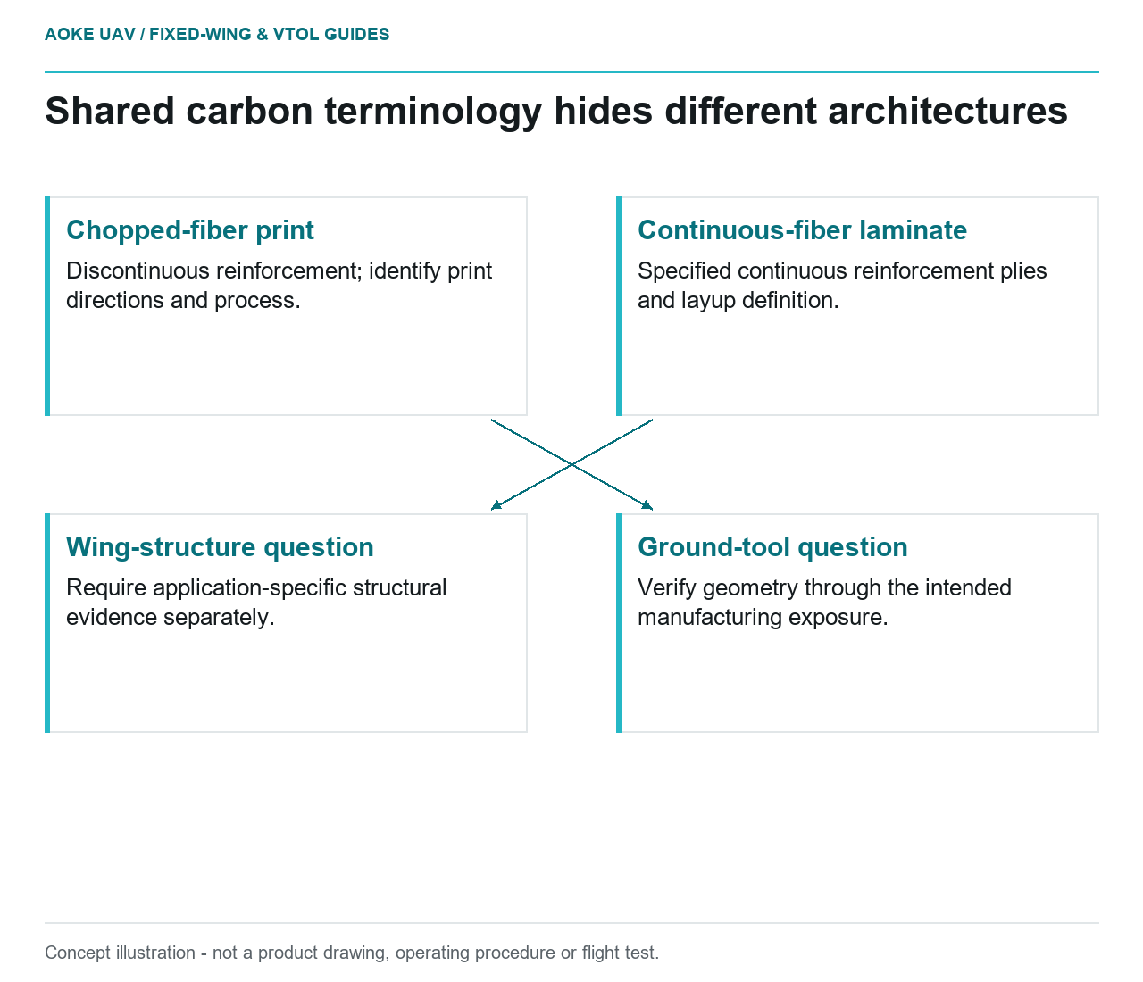
- Chopped-fiber print: Discontinuous reinforcement; identify print directions and process.
- Continuous-fiber laminate: Specified continuous reinforcement plies and layup definition.
- Ground-tool question: Verify geometry through the intended manufacturing exposure.
- Wing-structure question: Require application-specific structural evidence separately.
Imagine a civil mapping program comparing a printed wing tool with the laminate it will help manufacture. Both are described as carbon composite. That description leaves the decisive question unanswered: what material architecture and controlled process does each item actually use? This hypothetical large fixed-wing example is a comparison framework, not evidence that either candidate has demonstrated structural capability.
Reinforcement form and load transfer
For this discussion, chopped-fiber printing means a feedstock containing discontinuous reinforcement; a continuous-fiber wing laminate means a specified arrangement of continuous reinforcement plies. Those are definitions, not a strength ranking. Ask the supplier to confirm that its actual process matches the description before comparing anything. A marketing category cannot establish reinforcement length, constituent proportions, interfaces, or the finished part configuration.
The FAA composite-structure guidance emphasizes that mechanical behavior depends on fabrication methods and that material procurement and processing require control. Its aircraft-certification context does not provide properties for an unspecified printed feedstock. The useful lesson here is to request the relevant material and fabrication definition, rather than borrow laminate evidence because the trade names share a carbon label. [1]
Print direction versus laminate architecture
Stratasys identifies build orientation as an influence on surface quality, manufacturing effort, and performance because FDM properties are directional. That statement concerns its tooling process; it does not characterize every fiber-filled printer material. A meaningful comparison would identify the printed orientation and toolpath alongside the laminate layup definition, instead of listing a single unqualified strength number for each. [3]
In the proposed fixed-wing review, use separate drawings for the mold and wing. Mark the tool manufacturing directions on one and the specified laminate architecture on the other. Then ask what each reported measurement represents: a feedstock specimen, printed coupon, laminate coupon, representative feature, or complete assembly. Treat an unanswered question as missing evidence, not an invitation to assume equivalence.
Tooling application versus structural role
The printed object in this scenario supports a manufacturing operation; the wing is intended to carry flight loads. These are different acceptance problems even when the tool surface defines the wing geometry. Review the mold against its layup, thermal, pressure, sealing, and dimensional requirements. Stratasys explicitly organizes tooling decisions around those process conditions and anticipated use, rather than around a composite material label alone. [3]
For the wing, require the responsible engineering authority to establish its own structural evidence and manufacturing controls. A successful tool inspection cannot release the resulting aircraft structure. Conversely, demanding an airborne-part qualification label is not a substitute for verifying that a ground tool preserves the required shape throughout its actual manufacturing cycle. Keep the two review records linked but their decisions separate.
Evidence required for each comparison
Start a comparison sheet with the question being answered. If the question is tool accuracy, request finished-surface inspection and relevant processing-condition evidence. If it is wing capability, request the application-specific structural substantiation defined by the design authority. Match specimen geometry, conditioning, loading direction, and manufacturing state before interpreting any reported property. These are proposed review questions, not test outcomes or material allowables.
No chopped-fiber or continuous-fiber candidate dataset is established by the sources used here, so no numerical ranking follows. For a large fixed-wing program, the defensible decision is narrower: distinguish architectures, identify each intended function, and document the evidence missing from the proposed substitution. That preserves the usefulness of additive tooling without turning shared terminology into an unsupported claim about an aircraft wing.