Concept illustration
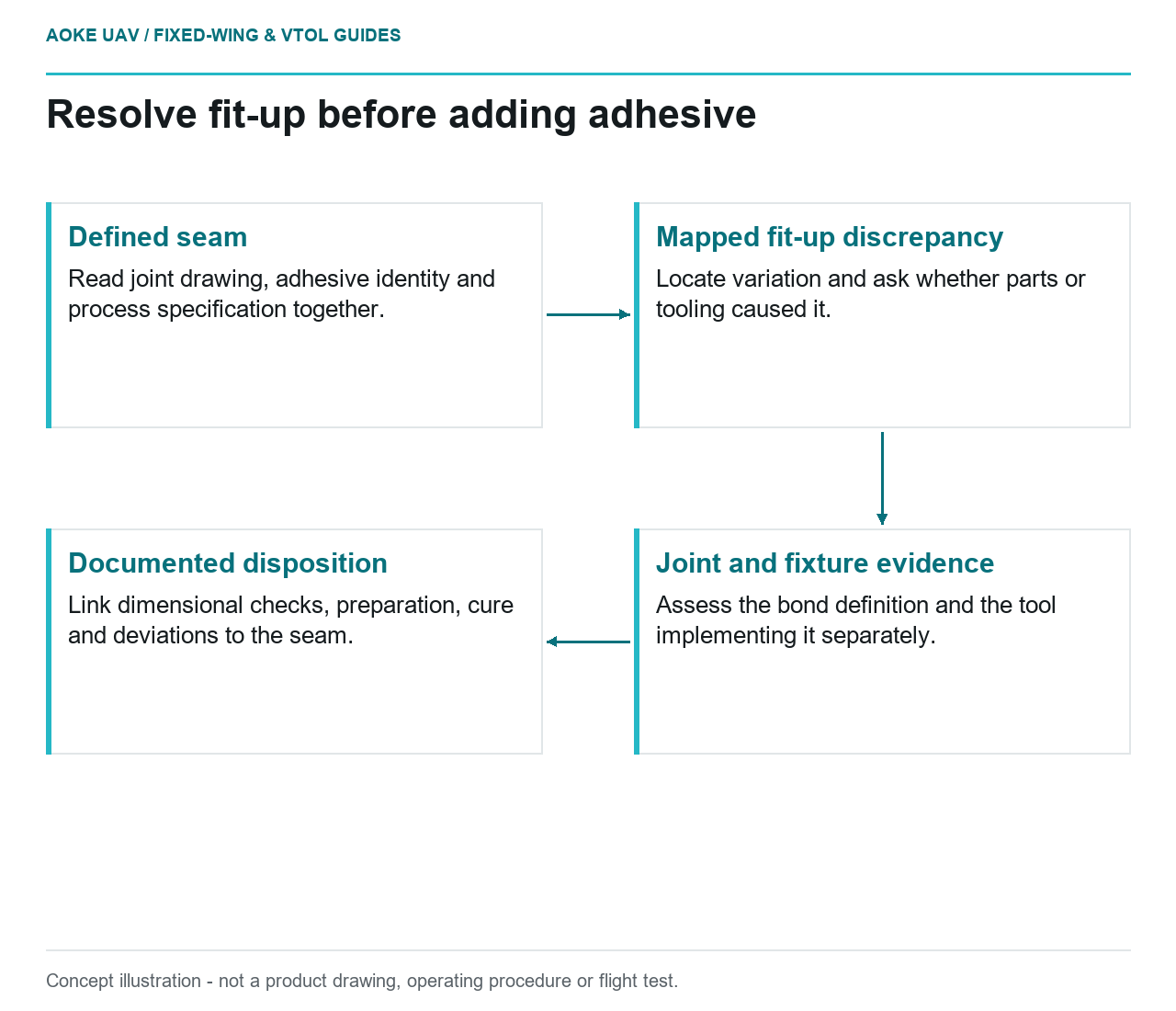
Read diagram notes
- Defined seam: Read joint drawing, adhesive identity and process specification together.
- Mapped fit-up discrepancy: Locate variation and ask whether parts or tooling caused it.
- Joint and fixture evidence: Assess the bond definition and the tool implementing it separately.
- Documented disposition: Link dimensional checks, preparation, cure and deviations to the seam.
A hypothetical long wing seam does not fit uniformly before bonding. The production proposal is to add adhesive wherever the gap appears larger. For a large fixed-wing civil survey aircraft, the review question is whether the proposed fit-up remains within the qualified joint and process definition. It cannot be answered by a universal statement that more adhesive means more strength. This article concerns geometry and process evidence, not a bonding recipe, adhesive selection or permission to close an out-of-tolerance wing assembly.
Joint geometry and process specification
Request the joint drawing, adhesive identity and applicable process specification together. Ask which surfaces define the intended separation, what variation is allowed and how that variation was represented in substantiation. Keep the definition of the bondline separate from the appearance of squeeze-out outside the joint. No thickness value is established here.
FAA guidance explicitly includes mating-part dimensional control, adhesive application, clamp-up pressure and bond-line thickness among controlled bonding considerations. It links those controls to qualified processes and structural substantiation. [1] The scope is US certificated aircraft, not this fixed-wing UAV. The transferable review principle is to ask which controlled definition the proposed seam follows, rather than substitute a convenient generic gap from another material system.
Gap variation along long seams
In the hypothetical review, map where the fit-up differs from the drawing and retain the method used to assess it. Ask whether the variation comes from the mating parts, the tool setup or another identified source. Avoid treating adhesive addition as the first disposition before the discrepancy itself has been defined.
NASA JSC’s sandwich assembly specification provides a concrete example of drawing-linked core fit checks and controlled adhesive processing for its own assembly types. It also ties cure schedules to applicable material and engineering documents. [2] That source illustrates the structure of a controlled process; it does not authorize copying its local mismatch provisions into this wing seam. Ask the aircraft designer to state what evidence covers the actual geometry, adhesive and substrates.
Spacers and cure tooling as controlled features
If the proposed process uses spacers or tooling to establish the gap, ask how those features are identified and how their effect was qualified. Identify the inspection opportunity before the interface becomes inaccessible. Do not recommend spacer material, bead size, clamp spacing or curing pressure without the applicable process data.
For this industrial fixed-wing assembly, distinguish two approvals: the defined bond process and the fixture implementing it. A precise tool cannot make an unsubstantiated joint geometry acceptable. Conversely, a qualified joint definition does not show that a newly changed tool reproduces the intended configuration. FAA guidance emphasizes repeatability, process limits and control of bonding variables. [1] Use those topics to request the relevant records rather than turn the fixture drawing into a substitute bonding specification.
Verification tied to the chosen adhesive system
Request a record connecting the seam to substrate preparation, adhesive batch, dimensional checks, cure documentation and any dispositioned deviation. Ask what the specified inspection can detect and which quality attributes rely on process control. FAA guidance explains that final inspection and proof loading do not replace a qualified bonding process or its long-term durability evidence. [1]
The hypothetical fixed-wing team should close the review with an explicit answer to the fit-up discrepancy, not a statement that the joint contains plenty of adhesive. NASA’s process verification example also links inspection points and traceable records to the invoked process level. [2] Neither document supplies an acceptable gap for this aircraft. Leave that numerical requirement with the actual design authority, and preserve the difference between a conforming process record and a claim of whole-wing strength.