Concept illustration
Read diagram notes
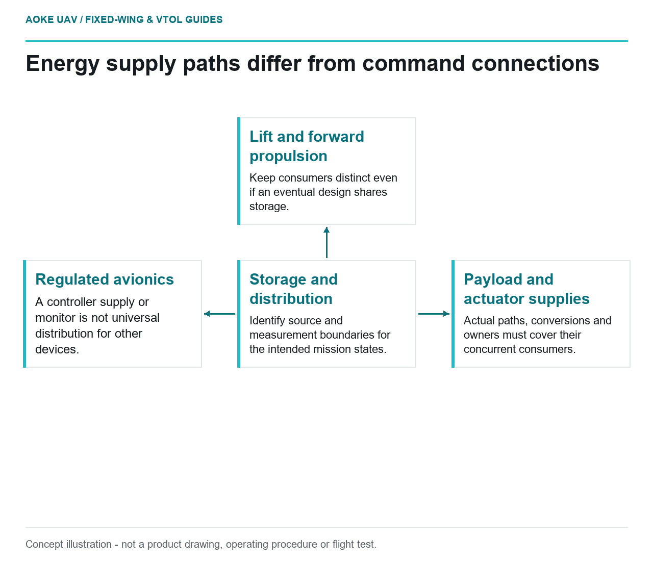
- Storage and distribution: Identify source and measurement boundaries for the intended mission states.
- Lift and forward propulsion: Keep consumers distinct even if an eventual design shares storage.
- Regulated avionics: A controller supply or monitor is not universal distribution for other devices.
- Payload and actuator supplies: Actual paths, conversions and owners must cover their concurrent consumers.
A propulsion shopping list is not yet an aircraft power architecture. For a large industrial fixed-wing UAV, the useful starting question is what must receive power, during which mission states, through which interfaces. A component can look attractive in isolation while leaving the payload supply, control electronics or transition demand undefined. This article proposes an original integration workflow, not a tested aircraft design or a component recommendation.
Separate mission phases and subsystem loads
Consider a hypothetical civil mapping aircraft with a removable sensor bay and separate vertical-lift and forward-thrust systems. Nothing here describes an GAUTEN product or flight result. Begin its requirements sheet with ground preparation, vertical departure, transition, climb, mapping cruise, return and recovery. Against each state, record which loads are active, their expected duration and whether the estimate comes from a supplier document, measurement or unresolved assumption.
ArduPilot describes QuadPlane as a combination of fixed-wing and multicopter capabilities. That architecture example is useful vocabulary, not evidence that a particular large aircraft has adequate power or acceptable handling.[2] In the hypothetical worksheet, therefore, keep lift motors and cruise propulsion as separate consumers even if they eventually share an energy source. Do not replace the phase sheet with one figure labelled maximum aircraft power.
Draw power paths, not just signal connections
Propose a diagram showing energy storage, distribution, controllers, propulsion motors, regulated avionics supplies and payload conversion. Mark where voltage and current will be measured. A line carrying a control command is not evidence that the commanded device receives an adequate supply. Give each branch a named interface owner and a documentation reference rather than assuming the autopilot connector settles the electrical design.
The Common Power Module documentation describes both autopilot supply and battery voltage/current monitoring, but warns that the example module cannot supply servos or other high-current devices.[3] Treat that as an example of why functions must be distinguished. Its legacy specifications are not a distribution-system design for this aircraft. For the proposed sensor bay, ask separately who supplies the camera, who supplies any actuator and which measurement actually includes those consumers.
Include installed mass and integration interfaces
As an editorial review method, compare complete architectures on the same configuration basis: batteries, controllers, motors, propellers, mounts, wiring, converters, cooling provisions and payload equipment. List provisional masses as provisional. A lightweight motor comparison is incomplete if one alternative’s mounting or conversion hardware has disappeared from the ledger. Likewise, specify which drawing revision defines the installation rather than assuming a catalogue photograph captures its interfaces.
maxon’s motor guide distinguishes electrical input from mechanical output and describes operating ranges and thermal limits.[1] It supplies generic electromechanical concepts, not applicable propulsion ratings for the hypothetical UAV. The architecture review should consequently request input-side evidence for the electrical budget and output-side evidence for the mechanical task. Neither a motor’s headline output nor its no-load speed should be substituted for measured aircraft consumption.
Ask for evidence from the complete system
Organize the next review around traceable questions. Which simultaneous-load combinations have evidence? Where are conversion losses accounted for? Which branches remain powered in each documented state? What establishes that monitoring covers the loads included in the prediction? These are proposed acceptance questions; answers must come from the actual aircraft and component documents, not from this explainer.
For the mapping scenario, make the deliverable a phase-by-branch table linked to the architecture drawing and a list of unresolved supplier requests. Associate every predicted demand with configuration, duration and environmental assumptions. Keep a change log when the payload or recovery concept changes, so earlier comparisons are not silently reused against a different aircraft.
The practical outcome is a better-defined procurement problem, not an endurance promise. Large fixed-wing integration becomes reviewable when propulsion, avionics and payload assumptions share one configuration record. Leave selection open wherever applicable evidence is missing; a clearly assigned unknown is more useful than a plausible component rating applied to the wrong task.
Related reading
- Tracking Structural Mass Growth During Payload Integration
- Fixed-Wing Mapping Starts With the Deliverable