Concept illustration
Read diagram notes
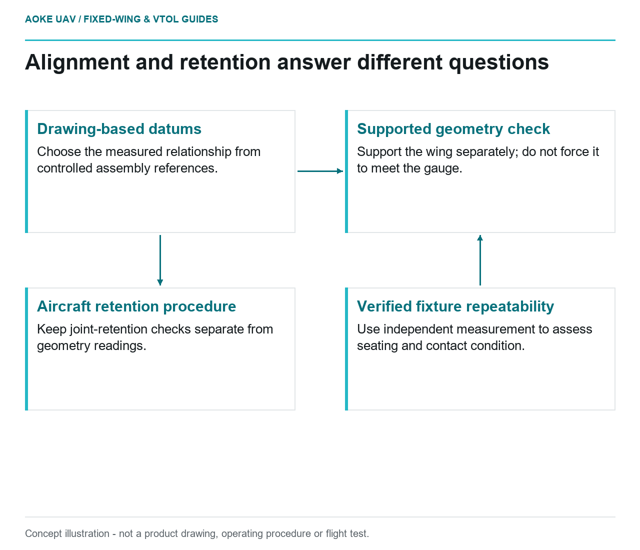
- Drawing-based datums: Choose the measured relationship from controlled assembly references.
- Supported geometry check: Support the wing separately; do not force it to meet the gauge.
- Verified fixture repeatability: Use independent measurement to assess seating and contact condition.
- Aircraft retention procedure: Keep joint-retention checks separate from geometry readings.
A hypothetical civil mapping workshop wants to check the removable wing roots of a multi-meter fixed-wing aircraft. The proposed printed fixture is intended to make geometry checks repeatable during ground assembly. It is not a test of retention strength. This scenario is original editorial reasoning, not an GAUTEN installation, and the fixture dimensions and aircraft acceptance limits must come from the project’s controlled engineering definition.
Choose datums from assembly drawings
Begin by writing the measurement question: which relative positions must be checked, in what assembly condition, and against which references? In this scenario, the wing-root interface, not the convenient outside of a fairing, would define the proposed datum scheme. The responsible engineer must identify the actual drawing references; this article cannot select them for an unknown airframe.
Formlabs recommends incorporating inspectable reference geometry into fixtures and checking printed dimensions against the CAD model with suitable metrology. It also calls for a functional seating test. These are relevant fixture-development practices, but the guidance provides no detachable-wing tolerance or structural acceptance criterion. [2]
Keep the fixture model linked to the assembly drawing revision. Mark which contacts locate, which support and which only protect surfaces. If two contacts appear to control the same motion, ask the reviewer to explain the intended contact sequence rather than relying on an operator to discover a compromise.
Support span without forcing alignment
For this large fixed-wing assembly, propose separate support for the long wing section so that the root check does not double as an improvised lifting method. The review should ask whether the support arrangement changes the condition being measured. Document the assembly state and handling arrangement rather than treating a photograph of a seated wing as sufficient evidence.
Formlabs describes functional testing of how the workpiece seats against locating surfaces and supports, and advises determining clamping needs from the operation’s forces. Its recommendations are tool-design guidance, not a reason to pull an aircraft joint into position with a stronger clamp. [2]
A useful hypothetical stop rule is therefore qualitative: if the operator must force the assembly to meet the gauge, stop and investigate the fixture, part and setup separately. Do not file the wing interface or tighten retention hardware merely to obtain a pleasing fixture reading. Those changes require their own approved engineering disposition.
Gauge repeatability and wear
Plan a fixture check that can distinguish repeatable location from a single successful fit. For example, the project could define a documented remove-and-reseat exercise with independent measurements. The number of repetitions, allowable variation and measurement capability must be established for the actual assembly; no universal values are implied here.
The OEM guidance notes that continuously loaded SLA parts may creep and suggests metal or hybrid solutions in high-wear regions. It also recommends releasing clamping forces after secondary operations. These limitations make contact condition and storage practice relevant review topics for the proposed printed fixture. [2]
In the scenario, inspect locating faces for wear, identify replaceable contact elements where justified and specify what happens after a knock, repair or prolonged loaded storage. A replacement contact is not automatically equivalent merely because it has the same external shape. Its installed location needs to be checked against the fixture’s controlled references.
Record geometry independently of retention
Create separate fields for fixture verification, assembly geometry results and joint-retention checks. The first asks whether the gauge is trustworthy; the second records the aircraft measurements; the third belongs to the aircraft’s specified retention procedure. A pass in one field should not pre-fill another.
For the fixed-wing workshop, a useful handoff would identify the aircraft section, fixture revision, setup condition, measurement equipment and unresolved observations. Include readings that do not meet the expected pattern, rather than recording only a final pass label. Reinspection after repair or drawing changes should be explicit.
The fixture earns its place by making the geometry question easier to answer and harder to misunderstand. If its setup masks a mismatch, needs undocumented operator judgment or cannot itself be verified, redesigning the aid may be preferable to adding more inspection steps around an ambiguous result.
Related reading
- Removable Wing Joints for Multi-Meter UAV Transport
- Tail-Boom Joint Alignment and Composite Interfaces