Concept illustration
Read diagram notes
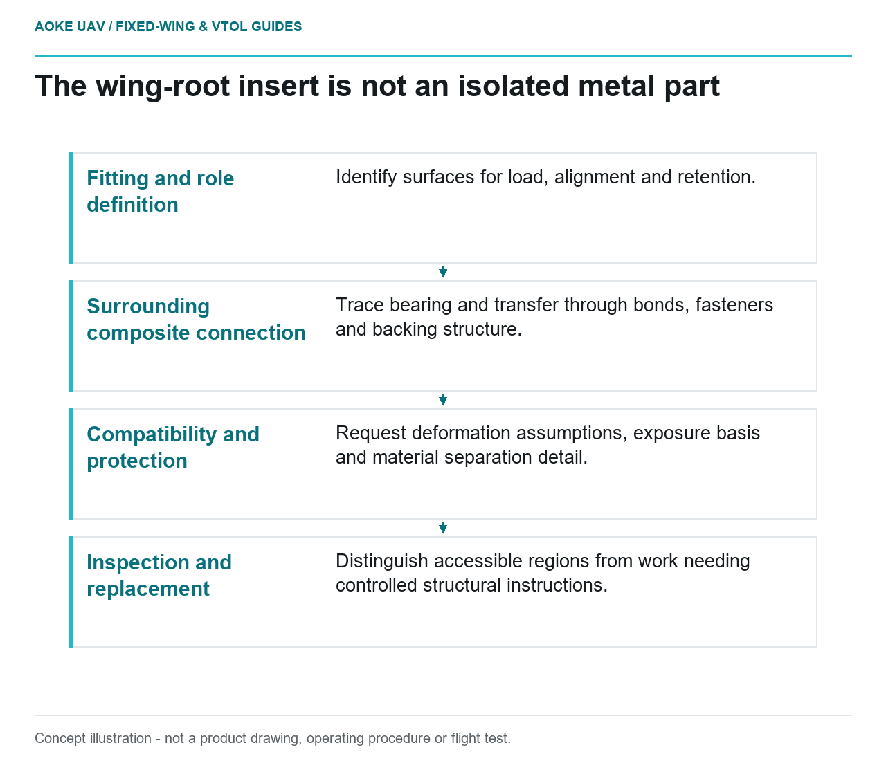
- Fitting and role definition: Identify surfaces for load, alignment and retention.
- Surrounding composite connection: Trace bearing and transfer through bonds, fasteners and backing structure.
- Compatibility and protection: Request deformation assumptions, exposure basis and material separation detail.
- Inspection and replacement: Distinguish accessible regions from work needing controlled structural instructions.
Look behind the finished fitting
A metal fitting at a composite wing root is a useful place to begin an interface review, not the end of one. Consider a hypothetical large industrial fixed-wing survey aircraft with detachable wings. Its root hardware appears robust, but the operator has only exterior photographs and a metal material certificate. The missing question is how the entire connection was substantiated, including the surrounding composite.
This is original review reasoning, not an GAUTEN product assessment. FAA composite guidance considers structural details, environmental exposure and material-process variability in substantiation. Its certificated-aircraft scope provides background for asking better questions; it is not evidence that this UAV or a particular insert is approved. [1]
Identify the actual load introduction
Request a section through the fitting and the adjacent laminate. Ask the designer to identify which surfaces carry load, which maintain alignment and which provide retention. Include any bonded interface, fastener group, backing structure or intermediate piece in the explanation. Do not treat an insert as an isolated metal part if the assessment depends on its surroundings.
For the hypothetical fixed-wing review, place local bearing and load transfer on the agenda as separate questions: where do contact reactions enter, and how are they transferred into the wing’s broader structure? Request the evidence covering those questions rather than estimating strength from bolt diameter or metal grade. FAA identifies holes and joints as configuration-specific structural details and stresses representative analysis and testing. [1]
Ask how compatibility was represented
A useful review drawing should show the insert’s termination and any changes in the nearby composite detail. Ask which deformation assumptions the joint model makes and whether the supporting test represents the actual arrangement. This is a proposed inquiry into stiffness compatibility, not a universal claim about a failure location or a recommended taper.
FAA discusses environmental effects on stiffness and strength and identifies residual stresses associated with differential thermal expansion of attached parts as a configuration-dependent issue. Consequently, a room-temperature material certificate alone does not answer every interface question. Ask which temperature and moisture exposures were considered for this aircraft’s construction and service assumptions. [1]
Keep the answers bounded by the evidence. If only a coupon is available, record the coupon’s materials and process, then ask what connects that result to the actual fitting. Do not silently promote a small specimen into a complete wing-root substantiation.
Map environmental separation and entry paths
FAA specifically discusses isolation at some composite-metal interfaces to avoid corrosion, including carbon composite and aluminum as an example. It also identifies galvanic corrosion and composite damage among issues for special fasteners and their installation procedures. These are material-pair and installation considerations, not permission to choose a generic barrier from this article. [1]
For the proposed survey wing, ask what separates the actual materials, where that separation terminates and how its condition is inspected. Put possible moisture routes around fitting edges and penetrations on the drawing as questions for the responsible designer. Avoid assuming that an exterior paint finish demonstrates the condition of a hidden interface.
Make replacement and inspection realistic
Identify what can be seen before assembly, what remains accessible afterward and what must be removed for a detailed examination. Ask whether replacing the metal hardware leaves the surrounding composite unchanged or requires a controlled structural procedure. Do not infer replaceability merely because a fastener can be undone.
FAA guidance emphasizes field inspection and repair access, documentation for difficult damage types and substantiated bolted and bonded repair procedures. Its maintenance discussion distinguishes visible indications from characterization of hidden damage. [1] In the hypothetical fixed-wing workflow, request a practical access demonstration and the exact applicable instructions before accepting a claim of straightforward field service.
Close the evidence loop
The review deliverable should connect the fitting drawing, surrounding structural assessment, environmental provisions and inspection instructions. Record unsupported interfaces as open questions. No GAUTEN root geometry, material allowables or replacement criteria were supplied. The purpose is to expose what a tidy fitting conceals from a document review, not to declare that a particular metal or composite pairing is safe.
Related reading
- Removable Wing Joints for Multi-Meter UAV Transport
- Inserts and Bushings in Printed Assembly Fixtures