Concept illustration
Read diagram notes
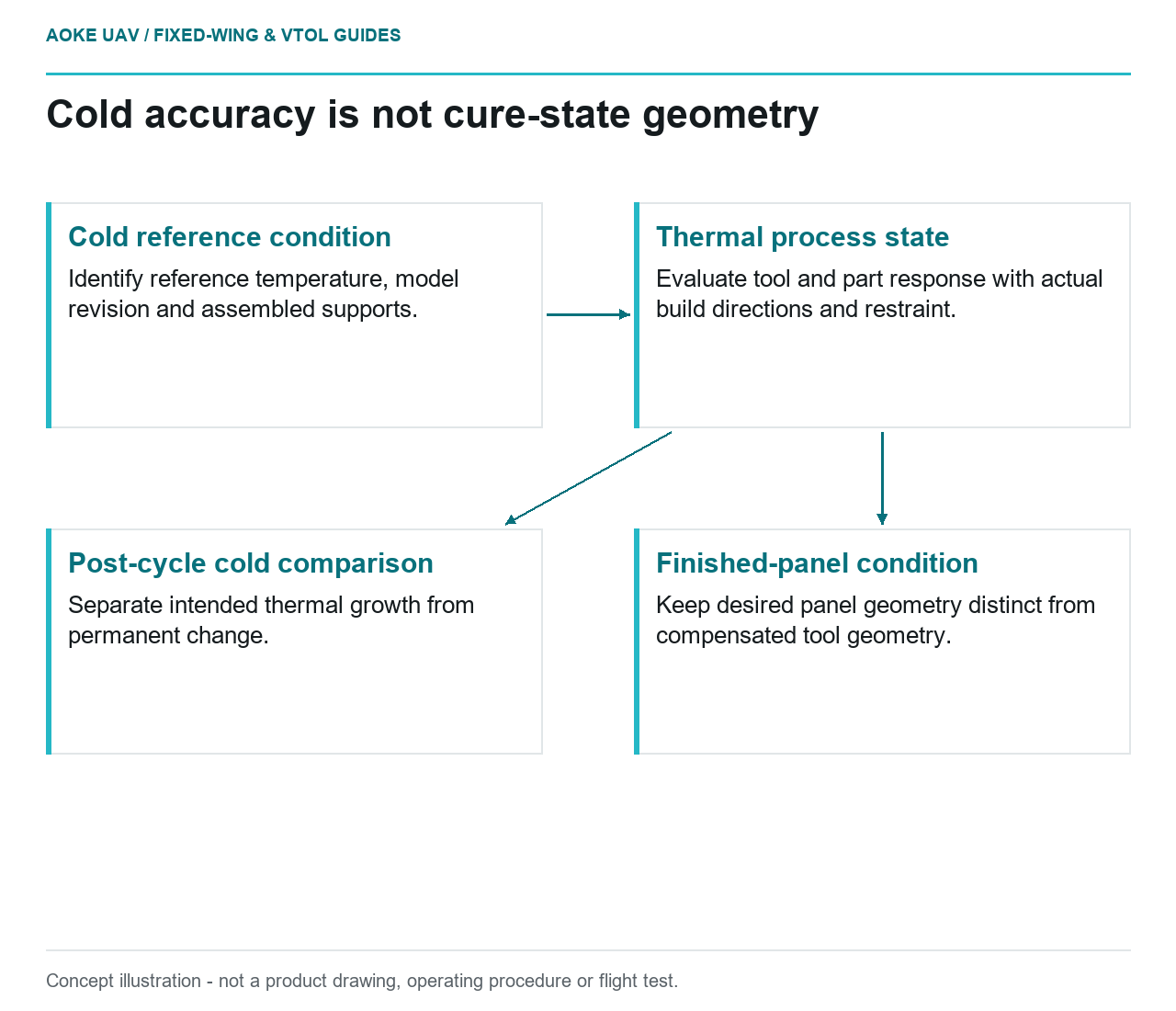
- Cold reference condition: Identify reference temperature, model revision and assembled supports.
- Thermal process state: Evaluate tool and part response with actual build directions and restraint.
- Finished-panel condition: Keep desired panel geometry distinct from compensated tool geometry.
- Post-cycle cold comparison: Separate intended thermal growth from permanent change.
A room-temperature inspection can establish one condition of a tool without describing its geometry during cure. Consider a hypothetical long printed mold for a large fixed-wing survey-aircraft skin. The team wants to know which geometry its inspection report represents and how that relates to the manufactured panel. This is an editorial integration scenario, not an GAUTEN tooling result, thermal test or proposed compensation value.
Tool and laminate expand differently
The Stratasys tooling guide identifies coefficient of thermal expansion as a design consideration because it affects the composite part’s final shape. Its compensation discussion includes both tool and part expansion, while its male- and female-tool discussion also considers demolding and residual-stress concerns. The guide is specifically about its FDM tooling applications. [1]
For the hypothetical fixed-wing mold, begin by defining the question more carefully than ‘does it match CAD?’ The project needs a reference temperature, an intended cure condition and a defined final-panel inspection state. Those conditions belong in the review record so that measurements taken at different stages are not treated as interchangeable.
Separate intended thermal growth from permanent change. A cold measurement before cycling, a measurement during a characterized thermal condition and a cold measurement after cycling would answer different questions. Which measurements are required must be decided by the tooling engineer using the actual process and measurement capability. No growth or stability result is asserted here.
Build direction and thermal response
Stratasys states that FDM parts are anisotropic, with build-related effects on mechanical properties and, to a lesser extent, thermal properties such as CTE. It provides material-specific flow and cross-flow information rather than one property for every printed polymer. That limits how far a generic datasheet value can be transferred to a different construction. [1]
In this large fixed-wing scenario, retain the build orientation and relevant material documentation as part of the tool definition. If the mold consists of segments built differently, ask how the assembled response will be evaluated. A value associated with a material family is not a measurement of the finished joined tool.
Review the supports and attachments at the same time. The proposed assessment should explain which features locate the mold and what movement the assembly arrangement permits during its specified cycle. This is a request for engineering analysis, not an instruction to add sliding joints or loosen supports on an existing tool.
Cure reference conditions
The OEM guide presents a thermal compensation approach using starting and cure temperatures with tool and part expansion properties. Its worked example belongs to its stated material and cure assumptions. Copying the example’s scale factor into an unrelated wing mold would discard the conditions that make the example meaningful. [1]
For the hypothetical project, specify which CAD geometry represents the desired finished panel and which represents the compensated tool. Keep the relationship explicit through later machining and sealing. A dimensional report should identify the model revision it actually compares against, not simply state that the tool is within tolerance.
Ask where the temperature information comes from and whether it represents the relevant tool regions. The actual characterization plan needs to address the process rather than assuming uniform conditions from a single nominal oven setting. This article supplies no sensor layout, soak time, cure temperature or mathematical allowance for a flight structure.
Evidence from the actual material and process
The guide’s scope matters: unless otherwise noted, its data and recommendations are based on a stated ULTEM resin and slice height. It also describes geometry-dependent accuracy and thermal-stability testing of representative tools. Those boundaries make the document useful for framing evidence requests, not for guaranteeing a new mold’s dimensional behavior. [1]
The fixed-wing team should therefore request the selected material and build documentation, final assembled geometry record, support configuration, intended process envelope and a justified characterization method. Any repaired joint or changed surface stack should be reviewed for its effect on that evidence chain before the earlier conclusion is reused.
The final decision should distinguish what is measured, what is predicted and what remains unverified. If the evidence only covers room temperature, say so. That is a more useful engineering statement than declaring a long printed wing mold thermally compensated because its cold surface looks accurate.