Concept illustration
Read diagram notes
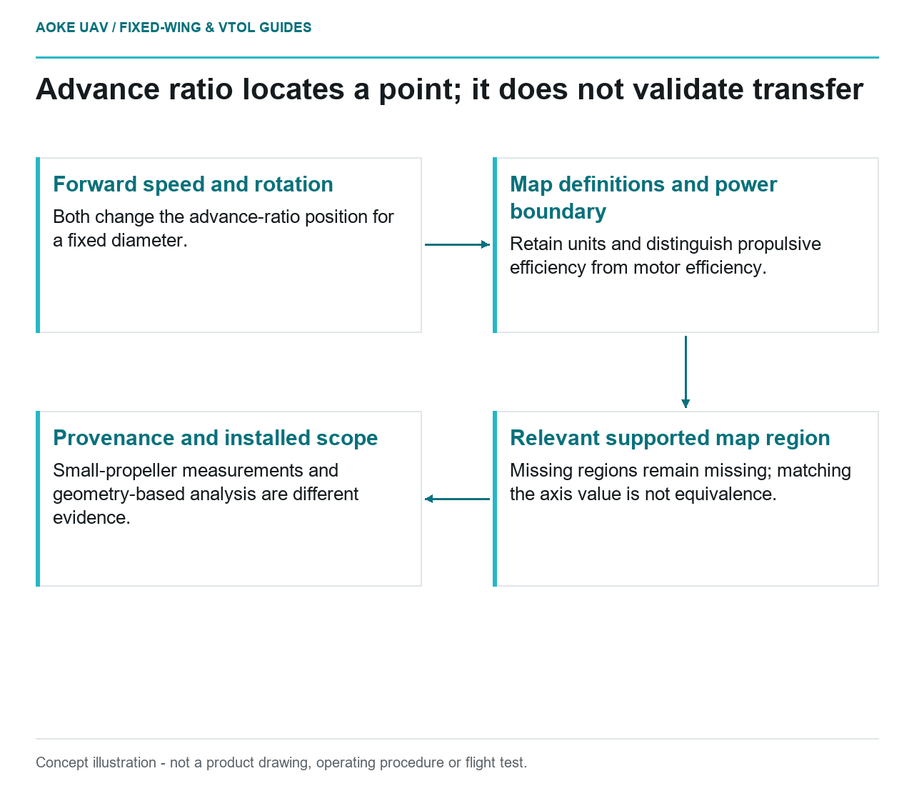
- Forward speed and rotation: Both change the advance-ratio position for a fixed diameter.
- Map definitions and power boundary: Retain units and distinguish propulsive efficiency from motor efficiency.
- Relevant supported map region: Missing regions remain missing; matching the axis value is not equivalence.
- Provenance and installed scope: Small-propeller measurements and geometry-based analysis are different evidence.
A propeller map is more informative than one thrust number, but only when its axes and definitions are understood. For large industrial fixed-wing integration, the immediate task is to locate the relevant operating condition without claiming more than the underlying data establish. A map can organize questions well before it can substantiate an installed aircraft.
Define variables and units first
The basic-relations figure on the UIUC Propeller Data Site defines advance ratio as J = V/(nD), with rotational frequency n expressed in revolutions per second.[8] Here V denotes forward speed and D propeller diameter. Use compatible length units for V and D and preserve the source’s rotational-frequency convention. Substituting an unconverted revolutions-per-minute label would not reproduce the defined quantity.
The same figure expresses propulsive efficiency as thrust times forward speed divided by power, and also relates it to the thrust coefficient, power coefficient and advance ratio.[8] Those definitions are a reading aid, not a motor or battery efficiency guarantee. Before using a downloaded map, identify the source’s power boundary and confirm what each column represents. Do not assume that similarly named quantities from different suppliers have identical measurement boundaries.
Locate mission points without inventing performance
Consider a hypothetical large fixed-wing aircraft being proposed for a civil corridor survey. The team receives a propeller map and wants to discuss climb and mapping cruise. This is an original editorial scenario, not an GAUTEN configuration. Ask for the intended forward-speed and rotational-speed ranges, the exact propeller identity and the atmosphere supporting the proposal. Mark intended mission points as requirements or predictions, not measured aircraft states.
As a map-reading exercise, changing forward speed while retaining rotational frequency and diameter changes advance ratio; changing rotational frequency can also change where the point lies. That follows from the source definition.[8] It does not mean that a matching advance ratio alone proves equivalent performance between different propellers, sizes or installations. Keep the other data conditions beside the point rather than using J as a universal similarity certificate.
Inspect what the source actually provides near the proposed point. A missing region should remain missing. Any proposed interpolation or model extension needs its method and applicability documented separately. Avoid extending a plotted curve merely because its last visible segment looks smooth. No operating point, allowable speed or aircraft capability is calculated in this explainer.
Distinguish measurements from predictions
UIUC describes its portal as wind-tunnel measurements for small UAV and model-aircraft propellers.[8] APC’s Performance Data page instead describes a proprietary analysis based on actual geometry and says performance-file headers include software version and simulation date.[9] Preserve those provenance differences. A plotted line is not automatically experimental, and an experimental point is not automatically an installed-aircraft result.
For the corridor-survey review, record file identity, propeller designation, version information, conditions and the selected region. If measured and predicted information disagree, first determine whether geometry, definitions and operating conditions align. Do not average unlike results into a supposedly stronger answer. The discrepancy itself may identify the supplier clarification that is needed.
Respect scale and installation boundaries
The small-propeller scope of the UIUC measurements is explicit.[8] Use this source to learn how evidence is described, not to choose a large propeller or promise cruise performance for the hypothetical aircraft. Request data applicable to the actual proposed component, followed by evidence addressing its installation and the aircraft demand. Familiar axes do not eliminate that requirement.
A useful map review ends with an annotated evidence record: definitions understood, relevant regions identified, provenance retained and unsupported transfers rejected. That is a meaningful integration deliverable even if the component selection remains open. For large fixed-wing work, reading the map correctly is the beginning of substantiation, not its conclusion.