Concept illustration
Read diagram notes
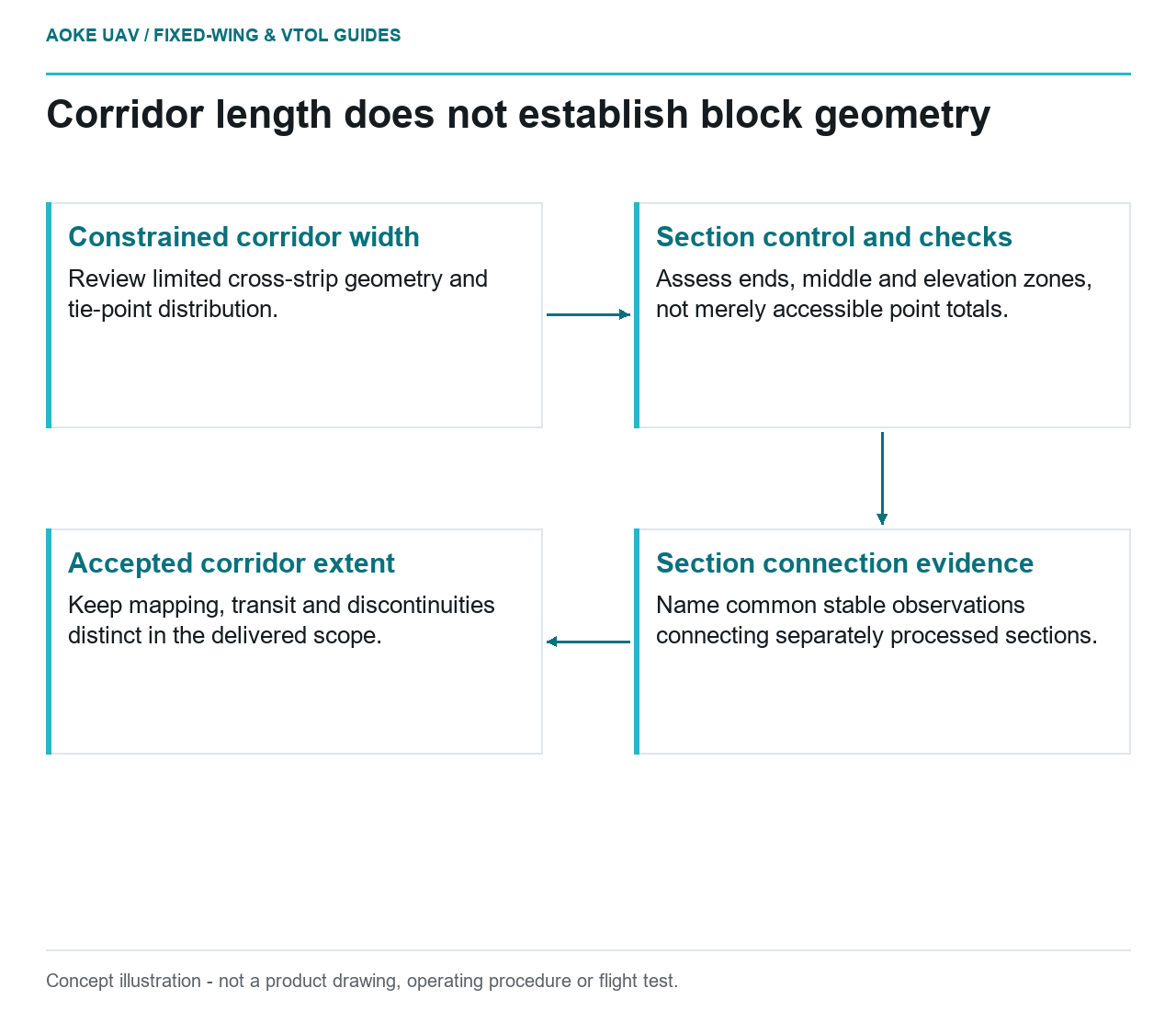
- Constrained corridor width: Review limited cross-strip geometry and tie-point distribution.
- Section control and checks: Assess ends, middle and elevation zones, not merely accessible point totals.
- Section connection evidence: Name common stable observations connecting separately processed sections.
- Accepted corridor extent: Keep mapping, transit and discontinuities distinct in the delivered scope.
Limited cross-strip geometry
A hypothetical large industrial fixed-wing UAV is proposed for mapping a long civil transport corridor. The mission appears straightforward because its length fits the route concept, but the survey team must still justify the image geometry. This article concerns the mapping block and its validation, not whether an asset defect is visible. Treat the corridor as a measurement design with constrained width, not merely a broad-area grid cropped to a long rectangle.
USGS describes camera self-calibration as a joint estimation of camera parameters and exposure orientation, with acquisition pattern and tie-point distribution contributing to the solution. It discusses orthogonal flights as a way to strengthen calibration geometry. [1] Those recommendations provide context for asking what geometry the narrow corridor lacks; they are not a requirement to fly an unspecified large aircraft through a particular pattern or an assurance that additional strips will solve every problem.
Control distribution along the corridor
In the hypothetical review, plot the proposed ground control against the entire accepted data extent. Ask whether it supports the ends, middle and elevation changes of the corridor or is concentrated where roads make access convenient. Distinguish a point count from a distribution rationale. Have the survey specialist explain what observations will constrain each separately processed section and how the reference information remains consistent across section boundaries.
USGS emphasizes that spatial positioning and accuracy of ground control influence overall UAS data accuracy, and that control and tie points should be distributed in horizontal and elevation dimensions. [1] Apply those principles as review questions, not as a universal corridor target layout. Where a segment cannot be accessed, document that limitation and the proposed alternative evidence. Do not state that precise camera positions automatically eliminate the need to assess that segment.
Turns and discontinuous acquisition areas
Long civil corridors may be proposed as several acquisition areas in this fictional scenario. Create a segment register that distinguishes intended mapping, transit and turn space, and ask which images belong to each adjustment. Require a clear account of how adjacent accepted sections will connect. A route that links two areas does not, by itself, create suitable mapping observations between them; leave any discontinuity visible in the proposed deliverable extent.
For a large fixed-wing platform, review where survey alignment is established at each segment and what usable data will support the ends. Refer turn feasibility and operating permissions to the responsible flight team and applicable documentation. The mapping specification should not quietly impose a manoeuvre that has never been reviewed for the aircraft. Likewise, a flight-feasibility finding should not be described as evidence that a section boundary has sufficient photogrammetric support.
Checkpoints matched to the project
USGS distinguishes points used for calibration from points withheld for validation in its cross-validation example and explains that checkpoint accuracy limits the assessment. [1] For this hypothetical corridor, define independent checks that address the intended measurements and relevant segments. Ask whether an aggregate result could hide an inadequately represented end or a problematic elevation zone. Do not report adjustment residuals as if they independently tested the finished corridor product.
Write the acceptance record around the project’s actual questions: what was mapped, which geometric assumptions were used, where control was unavailable and where independent observations exist. Keep the check identifiers and section boundaries traceable to the delivered version. If the evidence supports only part of the requested measurement, qualify that part explicitly. The result is a defensible review structure for fixed-wing corridor mapping, not a fabricated demonstration of automatic accuracy or a generic promise that route length determines survey quality.
One useful corridor exhibit would assign a stable identifier to each accepted mapping section and show its control, reserved checks and connection to neighbouring sections. The reviewer could then distinguish a section with no independent observations from one whose observations were used in adjustment. Keep any bridge between processing sections explicit rather than implying continuity from the aircraft’s transit track. This is a suggested documentation design, not an observation about an actual corridor survey.
Related reading
- Ground Control Distribution for Large-Area UAV Mapping
- What Fixed-Wing Corridor Reconnaissance Can and Cannot Deliver