Concept illustration
Read diagram notes
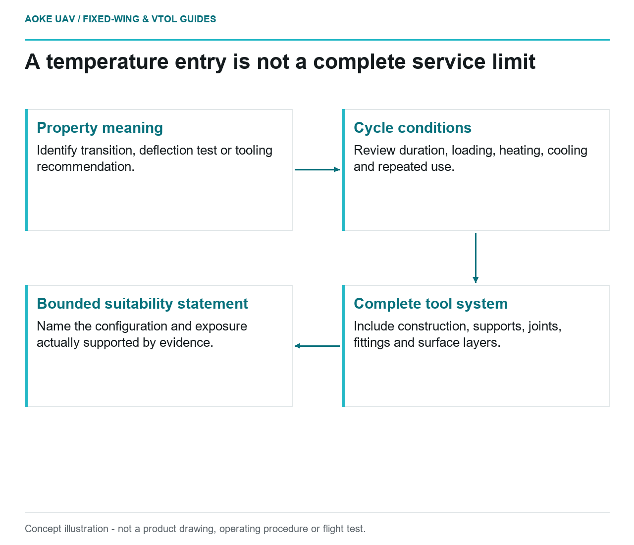
- Property meaning: Identify transition, deflection test or tooling recommendation.
- Cycle conditions: Review duration, loading, heating, cooling and repeated use.
- Complete tool system: Include construction, supports, joints, fittings and surface layers.
- Bounded suitability statement: Name the configuration and exposure actually supported by evidence.
A proposed printed cure tool for a large fixed-wing airframe panel arrives with a datasheet and a prominent temperature claim. In this hypothetical civil-aircraft project, the review question is whether the complete tool suits a sustained heat-and-pressure process, not whether the largest number looks reassuring. This article is original editorial reasoning, not an GAUTEN material selection, approved cure cycle or claim that a particular printed polymer is flight-qualified.
Datasheet properties answer different questions
Identify exactly what the cited number represents before comparing materials. Is the document reporting a glass-transition property, a test-specific deflection result or an application-specific tooling recommendation? Ask for the test conditions and intended interpretation rather than relabeling every temperature entry as a continuous service limit.
The Stratasys guide helps demonstrate the distinction: its materials table lists glass-transition information separately from recommended tooling uses and limitations. It also treats cure temperature, CTE, pressure, bagging and anticipated life as separate design considerations. Reading a single table cell would omit that wider application context. [1]
For this fixed-wing project, record the exact supplier document and the property being used to support the decision. If a proposal relies only on a melting-point claim, ask where the evidence for usable tool shape and stiffness throughout the actual cycle is documented. Do not manufacture a service limit by subtracting an arbitrary margin from that number.
Time and load during the cycle
The OEM guide presents elevated-temperature mechanical testing and separate tool-life and creep evaluations. Its flexural data show temperature- and orientation-related behavior for the identified material, while its discussion acknowledges limitations in the available creep-test configuration. These results are characterized evidence within the guide’s scope, not universal allowable values. [1]
In the hypothetical review, describe the full exposure that the tool must tolerate: heating, sustained processing, cooling and repeated use. Then ask whether the submitted evidence covers those conditions under relevant loading. A brief test or an unloaded material property should not be silently described as an assessment of the whole manufacturing cycle.
The resulting evidence table should separate measured data, supplier recommendations and project analysis. Where duration or loading differs from the supporting evidence, flag the difference for the responsible engineer. This article offers no extrapolation rule, allowable deformation or number of production cycles.
Pressure and support conditions
Stratasys distinguishes shell and sparse tool constructions and explains that consolidation pressure and bagging method affect their design. It specifically limits some construction guidance to its tested material, fill patterns and slice height. That is a warning against treating a generic infill label as proof of pressure suitability. [1]
For the proposed large fixed-wing panel, describe the complete pressure-boundary and support arrangement. Ask which surfaces see the processing environment, how the tool is supported and what evidence covers the chosen construction. The review should not assume that an attractive outer shell reveals the internal structure or its behavior.
Include joints, fittings and surface layers in that review. Their documentation may not match the base polymer’s apparent temperature capability. The goal is to establish the weakest substantiated part of the tool system through actual evidence, not to guess which component will fail first.
Validation of the complete tool
The Stratasys guide calls for sealers to be selected for cure exposure, expected tool life and compatibility with the printed material. Its cycling discussion reports degradation of a particular sealer even where the underlying printed tool showed different behavior. A resin datasheet therefore does not describe the entire surface system. [1]
A useful hypothetical validation proposal would identify the final tool configuration, intended cycle, joining and sealing records, dimensional checks and evidence needed before use. The project must decide the actual test methods and limits. A trial on a small unjoined sample may inform development without establishing that the full wing-panel tool is suitable.
End the review with a bounded statement: what configuration, exposure and intended use the available evidence supports, and which questions remain open. Keep tool suitability separate from acceptance of the composite panel and from release of the fixed-wing aircraft. None of those decisions is supplied by the temperature number printed most prominently on a datasheet.