Concept illustration
Read diagram notes
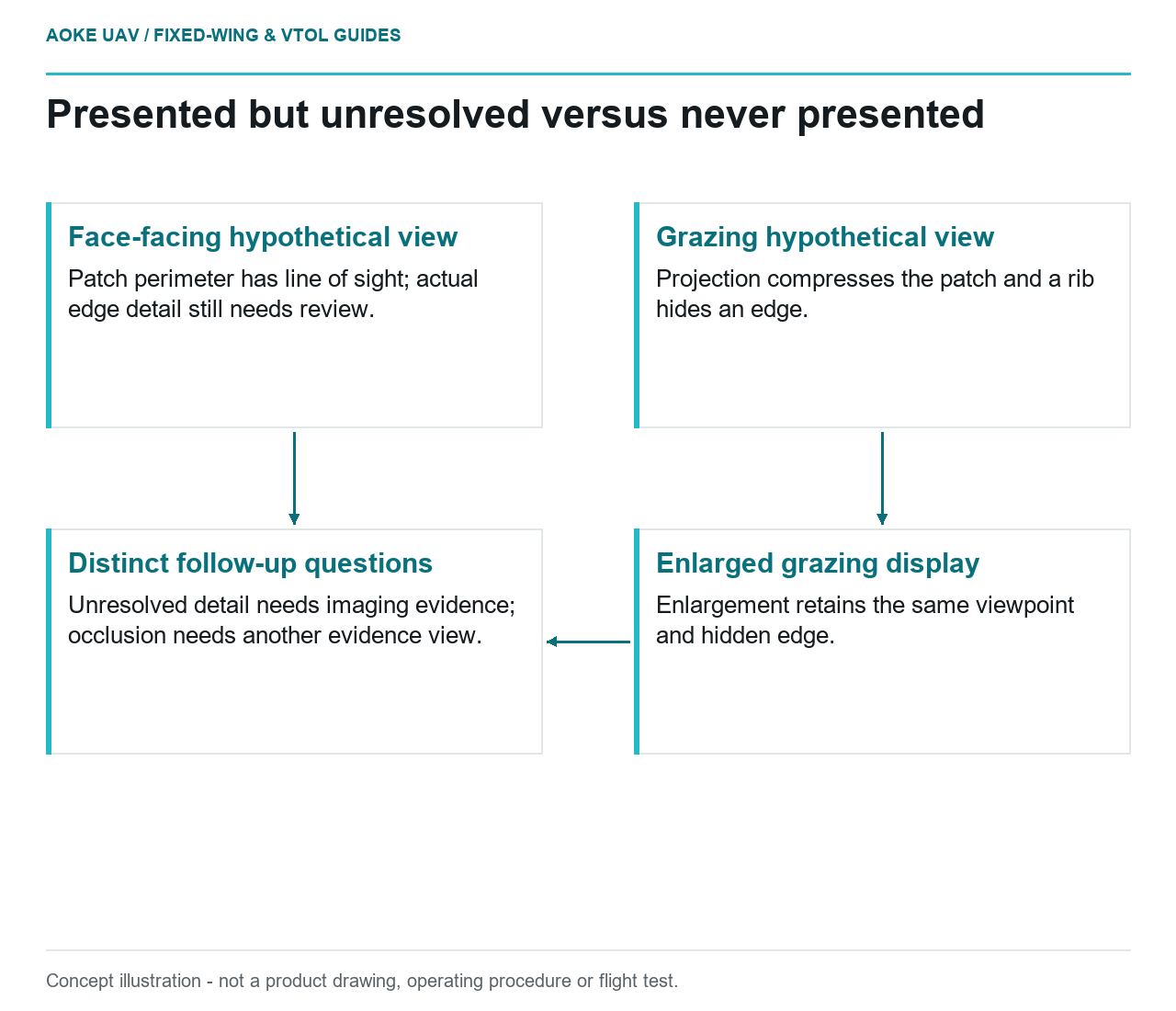
- Face-facing hypothetical view: Patch perimeter has line of sight; actual edge detail still needs review.
- Grazing hypothetical view: Projection compresses the patch and a rib hides an edge.
- Enlarged grazing display: Enlargement retains the same viewpoint and hidden edge.
- Distinct follow-up questions: Unresolved detail needs imaging evidence; occlusion needs another evidence view.
View angle and occlusion
Consider a hypothetical concrete retaining wall beside a civil transport corridor. The owner asks whether the visible outline of a rectangular repair patch is continuous around its perimeter, not whether the repair is structurally sound. A large industrial fixed-wing reconnaissance assignment already has a proposed observation geometry. Can that geometry show the whole patch boundary, or only the wall’s presence?
This is an original qualitative thought experiment, not an GAUTEN flight or a demonstrated camera result. Assume two candidate viewpoints have the same camera-to-patch range and elevation, unchanged optics and adequate pointing. Assume their feasibility and permissions have been assessed separately; neither is a route recommendation. View A faces the wall nearly squarely. View B looks along it at a grazing angle. A projecting wall rib stands beside the patch.
In this simplified scene, A presents the patch as a broad shape; B compresses its apparent width across the wall. From B, the rib also hides one patch edge. Compression is projection: a visible surface occupies a narrower image shape. Occlusion is different: the rib interrupts the line of sight. Even a perfectly sharp picture from B would not reveal that hidden edge. These are deductions from the stated scene, not measured inspection outcomes.
Sensor field of view and sample distance
Keep that comparison separate from resolution. The thought experiment holds range and camera configuration constant, yet changes what is presented to the sensor. A nominal ground-sampling figure for the corridor floor does not describe the patch’s grazing view. USGS calibration guidance treats camera orientation and object geometry through its collinearity model; its ground-control discussion also warns that small ground sample distance alone does not establish geometric accuracy. [2] Neither passage establishes a detectable repair-boundary size.
For this patch, the proposed comparison is therefore:
| View | Geometry in the example | Question left open |
|---|---|---|
| A: face-facing | All perimeter edges have unobstructed lines of sight. | Does the captured detail actually distinguish each edge? |
| B: grazing | Patch width is foreshortened; the rib hides an edge. | Visible edges may be assessed, but the full perimeter remains unobserved. |
| B: enlarged display crop | Same captured viewpoint and same obstruction. | A larger display does not reveal the edge behind the rib. |
The crop is a presentation change, not a third acquisition geometry. FHWA’s distance-versus-zoom experiment found that images initially appearing comparable showed different detail when enlarged; its digital-zoom example was unsuitable for assessing the defect while still indicating an area for further inspection. [1] That bounded result supports scrutinizing captured detail, not borrowing the experiment’s distances for a large aircraft.
Image quality at the required standoff
Now challenge A without changing the wall. Suppose its full patch perimeter is in view, but the boundary blends into the surrounding concrete. A has passed the line-of-sight question, not the image-quality question. Conversely, suppose B shows crisp concrete texture: that sharpness cannot establish continuity around the obscured edge. The useful distinction is between a boundary presented but unresolved and a boundary never presented.
FHWA illustrates exposure and motion-blur effects in its controlled imaging tests. [1] Applied to this hypothetical patch review, ask for original frames that retain both the perimeter and adjacent rib, alongside capture and processing information. A tight crop alone removes context needed to understand why an edge disappears. Compare edge locations in the original frame before interpreting an apparent break as an actual patch-boundary discontinuity. No shutter setting or minimum feature threshold follows from this example.
Scope a different method when needed
For a large fixed-wing assignment, do not turn A and B into instructions to orbit, hover or move closer. FHWA distinguishes fixed-wing mapping roles from inspections needing static positioning, within research on bridge-UAS data collection rather than qualification of this aircraft. [1] If the feasible acquisition only supplies B, the requested whole-perimeter observation remains unanswered regardless of display magnification.
The specific follow-up question is whether another owner-selected evidence method can expose the edge behind the rib. If A is available but unresolved, the question instead concerns demonstrated imaging detail. Neither outcome diagnoses repair condition. This separation lets the client reject an impossible view requirement without rejecting every useful fixed-wing observation of the wall and corridor.
Related reading
- Vertical Faces and the Blind Spots of Nadir Mapping
- When a New Payload Requires a Structural Reassessment