Concept illustration
Read diagram notes
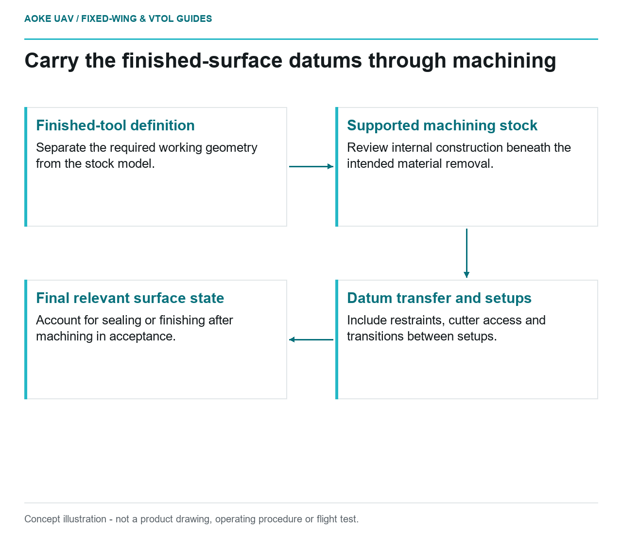
- Finished-tool definition: Separate the required working geometry from the stock model.
- Supported machining stock: Review internal construction beneath the intended material removal.
- Datum transfer and setups: Include restraints, cutter access and transitions between setups.
- Final relevant surface state: Account for sealing or finishing after machining in acceptance.
Printing the nominal shape is not always the intended endpoint. In a hypothetical large fixed-wing survey-aircraft program, a wing mold is proposed as a printed near-net body followed by controlled finish machining. The reader question is not which printer has the best headline accuracy. It is whether the complete print, support, machining and inspection route can deliver the specified working surface without an unverified assumption between stages.
Work backward from the finished surface
Stratasys describes oversize FDM tooling followed by skim machining when the as-printed result does not meet the tool requirement. Its guide also distinguishes ways to place additional material near the machining surface. [1]
For our fixed-wing mold, begin with the finished-tool drawing and its inspection datums. Identify the aerodynamic surface, flange interfaces and any locations where the tool must connect to other tooling. Decide which surfaces require machining and which need only another specified acceptance method. An attractive raw print does not remove a requirement from the drawing, and machining every accessible face is not automatically necessary.
Keep the intended surface definition separate from the stock model. Reviewers should be able to see the final geometry and the sacrificial machining volume independently. If the only surviving model combines both without clear identification, later inspection may compare the finished surface to the wrong revision.
Reserve supported stock, not just extra outline
The OEM guide discusses local reinforcement around machined faces and inserts, including separate bodies for localized material. It also recommends application-specific machining trials rather than assuming an example cutting setup transfers unchanged. [1]
Our proposed planning question is therefore three-dimensional: will the cutter remain within material that was actually designed to be removed, with a supported tool surface beneath it? Review the internal construction in the same coordinate system as the machining stock. An oversize outer envelope alone does not show what lies behind the final pass.
Check edges, transitions and tool joints separately from broad shallow surfaces. Establish who reviews a proposed change to the printed internal structure after the machining strategy has been agreed. A slicer revision that appears to save material should not bypass the stock-and-support review. No universal allowance or cutter setting is offered here; those values require the selected material, machine and verified machining route.
Transfer datums through the whole route
In this scenario, define a datum transfer record from printed body to machining fixture and then to finished-tool inspection. Show where the tool sits, how it is restrained and which features establish position. Check cutter and holder clearance with the support arrangement included, not with the mold floating alone in CAD.
For a long fixed-wing mold, also plan the transitions between setups if a single setup cannot reach everything. State how the team will compare adjacent finished regions and distinguish alignment error from surface-form error. The objective is not to prescribe a machining strategy from generic guidance, but to make the chosen strategy auditable before an expensive body reaches the machine.
Preserve evidence of the actual setup used during a trial. A successful local test cut can justify developing that operation further; it does not establish the finished shape of the entire tool. Review handling, restraint and inspection after each relevant change rather than assuming a local demonstration settles scale-up.
Inspect after the final relevant operation
Our recommended acceptance package would identify the finished surface state, measurement method, reference temperature where specified, and any sealing or finishing still to follow. If a coating is applied after dimensional inspection, define whether another check is needed. Do not silently treat the machined substrate and the final laminate-contact surface as identical.
The resulting decision is a route comparison: direct use of an as-printed tool, near-net printing with finish machining, or another tooling method. Compare the evidence burden and opportunities for correction, not only printer time. This OEM guide supports the concept of locally reinforced, machined FDM tooling; it does not qualify the hypothetical mold, supply UAV material allowables or authorize a wing manufacturing process.