Concept illustration
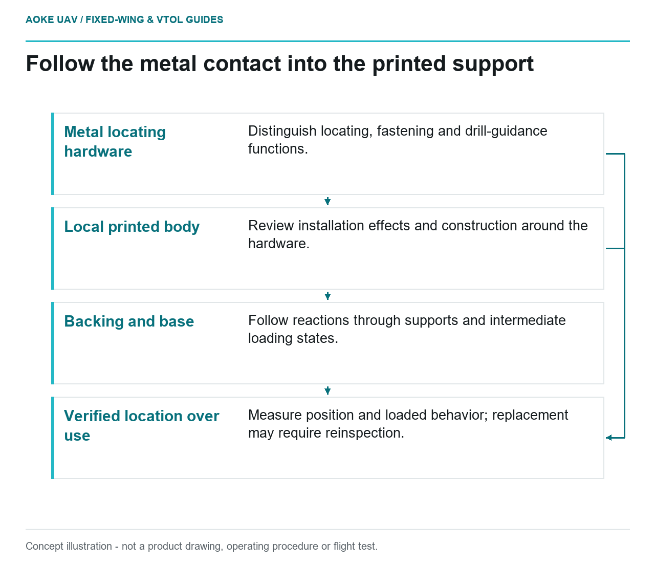
Read diagram notes
- Metal locating hardware: Distinguish locating, fastening and drill-guidance functions.
- Local printed body: Review installation effects and construction around the hardware.
- Backing and base: Follow reactions through supports and intermediate loading states.
- Verified location over use: Measure position and loaded behavior; replacement may require reinspection.
A metal bushing is not a complete fixture design. Consider a hypothetical wing-assembly station for a large industrial fixed-wing mapping aircraft. Operators repeatedly locate subassemblies against hardware mounted in a printed body. The proposal is to concentrate contact at replaceable metal features while retaining custom printed geometry elsewhere. The question is how to verify the entire location system, rather than assuming the metal component settles every wear and accuracy concern.
Define what the hardware actually controls
Formlabs recommends considering hybrid metal-and-print solutions at high-wear locations. Stratasys separately discusses localized reinforcement around tooling bushings and inserts. Both are manufacturing-tool guidance, not flight-hardware design approval. [2] [1]
In our fixed-wing fixture, distinguish a locating bushing from a fastening insert and from a drill-guidance feature. They can appear similar in a model while serving different functions. For each feature, record which direction it locates, where reaction loads go and what measurement will reveal movement. Do not assign the same acceptance check merely because every component is cylindrical.
Define whether hardware replacement should restore a known location or require a new fixture inspection. A replaceable item can still be a controlled item. Give the fixture body, contact hardware and assembly drawing linked identities so a workshop repair does not become an undocumented design revision.
Follow the load into the printed body
The OEM tooling guide’s reinforcement discussion connects local geometry to insert and bushing regions. It does not establish a universal wall thickness for this application. [1] Our review would therefore include the printed material surrounding the hardware, the backing arrangement and the connection to the fixture base.
For the long-wing station, evaluate the proposed loading sequence rather than only the fully assembled condition. A component temporarily supported at one locating point is a different fixture condition from a fully seated assembly. Identify those intermediate states before choosing an installation method. Record which surfaces are intended to carry contact and which clearances must remain clear.
Do not let a hard contact component conceal a poorly supported arm. Examine access for inspecting the body around the hardware after installation. If the retaining feature covers the only visible region where movement could be detected, decide how another inspection method will address that blind spot before accepting the design.
Use installation evidence for the actual combination
This explainer deliberately provides no interference fit, installation temperature, adhesive choice or tightening value. Those instructions require the selected hardware, printed material, process and geometry. The recommended evidence package would identify all four and state the installation inspection. A rule from a flight fastener installation or another polymer is not an acceptable automatic substitute.
Build a representative off-aircraft trial feature before committing the complete fixture. Preserve what was printed, how it was conditioned and finished, how hardware was installed and what changed afterward. Measure the feature relative to useful fixture datums rather than reporting only that it could be assembled.
If a proposed installation method damages or visibly distorts the local body, investigate the cause. Replacing the failed trial with another specimen until one looks acceptable would not establish a repeatable route. Agree acceptance criteria before the trial, including what evidence requires redesign rather than rework.
Inspect retention and location over use
Formlabs calls for both dimensional checking against CAD and functional fixture testing. [2] For our fixed-wing assembly station, those become separate records: the measured hardware location and its behavior during the intended handling and clamping sequence. An unloaded fit check does not answer every question about the loaded fixture.
We would define an inspection interval and review triggers based on an application-specific trial, without inventing a service-life number. Record looseness, replacement, local damage and datum changes against fixture identity. The release decision concerns a ground manufacturing tool only. It does not transfer insert rules to an aircraft structure or establish the airworthiness of a wing built using the fixture.