Concept illustration
Read diagram notes
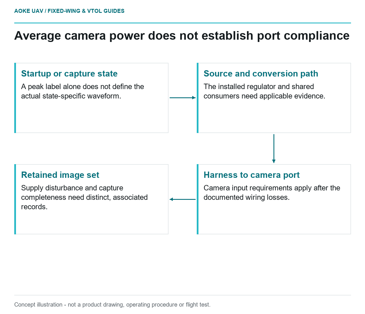
- Startup or capture state: A peak label alone does not define the actual state-specific waveform.
- Source and conversion path: The installed regulator and shared consumers need applicable evidence.
- Harness to camera port: Camera input requirements apply after the documented wiring losses.
- Retained image set: Supply disturbance and capture completeness need distinct, associated records.
A hypothetical large fixed-wing survey aircraft adds a camera to a shared equipment bay. The energy spreadsheet includes its average power, but the supply drawing does not identify what happens during startup or capture activity. The energy entry and the electrical integration argument answer different questions. This article focuses on the exact survey sensor’s supply requirements and data consequences, rather than the avionics controller’s own power architecture or a generic battery endurance calculation.
Startup and capture-state demands
Request the camera’s primary supply specification and the definitions behind any continuous, average or peak figure. Ask which states and durations the figures cover and which remain undocumented. Do not infer a startup waveform from a peak label alone. If a procurement sheet offers only one power number, identify the missing state-specific information instead of multiplying it by an arbitrary allowance.
The December 2021 RedEdge-P and DLS 2 integration guide distinguishes continuous and peak power and specifies supply compliance at the camera power port, accounting for wiring losses.[1] This is a model-specific example, not a rating source for an unidentified camera. It illustrates why a payload energy-budget entry cannot by itself establish the installed source, regulator and harness requirements.
Regulator and wiring interfaces
For the hypothetical fixed-wing bay, identify the source-to-camera path on a controlled drawing, including any conversion stage and detachable interface. Request the actual regulator and harness evidence for that arrangement. The relevant review boundary is the defined camera input, not simply the nominal source label. No universal regulator margin, wire size or connector rating is proposed by this article.
Do not assume that the flight controller’s supply is also available for the payload. The Pixhawk power example describes particular controller and servo paths rather than a universal survey-camera supply.[2] The actual aircraft distribution design must identify its consumers and supported interfaces independently. This keeps the camera question from being hidden inside a statement that the autopilot powers up correctly.
Interruptions and data consequences
Request the exact sensor documentation for behavior associated with supply disturbances and recovery. Which records indicate a restart or an unsuccessful capture? What evidence connects a power event to the retained image set? The cited example does not establish every consequence for the proposed aircraft, so this article offers no guaranteed recovery delay or claim that local files are preserved under all interruption conditions.
For the large fixed-wing survey workflow, keep electrical acceptance separate from the completeness of the delivered dataset. A power trace and an image inventory are different evidence items, and neither alone defines the other. Ask the responsible integration and survey teams how they document the association. This is a review question, not a procedure for interrupting power or conducting an in-flight fault experiment.
Exact sensor supply specification
A useful evidence package connects camera model and revision, applicable supply requirements, source and regulator identities, wiring configuration and the records supporting the installed claim. Include other consumers sharing the relevant branch where the actual design makes them relevant. Identify which simultaneous conditions have supporting evidence rather than assuming that independent component labels cover their combined use.
The resulting fixed-wing decision may confirm only that the available documents are insufficient, which is more useful than a guessed compatibility verdict. Missing transient definitions, an unidentified regulator or undocumented data behavior require different follow-up evidence. No sensor voltage, current allowance or protection setting is prescribed here. The aim is to connect the payload’s actual input requirements and output records to the aircraft installation, not to equate average watts with electrical compatibility.