Concept illustration
Read diagram notes
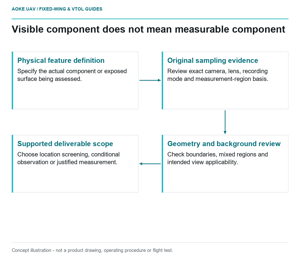
- Physical feature definition: Specify the actual component or exposed surface being assessed.
- Original sampling evidence: Review exact camera, lens, recording mode and measurement-region basis.
- Geometry and background review: Check boundaries, mixed regions and intended view applicability.
- Supported deliverable scope: Choose location screening, conditional observation or justified measurement.
A small component can stand out on a thermal display without providing a justified temperature measurement. Consider a hypothetical large fixed-wing survey of an industrial corridor. An analyst notices a bright point and wants to report a component temperature. Before doing so, the team needs to establish what part of the recorded signal actually represents that component. This is a civil integration example, not an GAUTEN detection result or a demonstrated payload capability.
Object size and thermal image sampling
FLIR’s distance-measurement guidance links measurement capability to camera resolution, field of view and how the target fills the measurement region. It explicitly distinguishes seeing a target from measuring it accurately. [4] That is the relevant principle; a general OEM example is not acceptance evidence for every camera, lens and airborne installation.
For the proposed workflow, define the physical feature before selecting a flight plan. Is the intended measurement the whole enclosure, a connection, or an exposed surface within an assembly? A proposal should not demonstrate visibility of the enclosure and then quietly promise temperatures for much smaller features inside it.
Request the exact camera and lens documentation, including instantaneous field of view and any separate measurement-field requirement. Ask how the integrator will demonstrate applicability to the recording mode actually used. Do not invent a universal pixels-per-target rule or treat a detector’s advertised image dimensions as a complete measurement specification.
Measurement region versus display enlargement
FLIR explains that digital zoom enlarges existing pixels rather than improving the ability to measure a small target. [4] A report should therefore distinguish a cropped presentation image from evidence that the original frame sampled the component adequately.
Require an original thermal frame alongside any enlarged illustration. Mark the proposed measurement region and retain the asset-identification evidence. An analyst should be able to show where the region falls in the raw record, not simply point to an attractive patch in a slide. If the component’s boundary cannot be established, do not conceal that fact by drawing a confident box.
For a large fixed-wing mission, the review should include representative straight acquisition segments and any views accepted near strip edges. This is a proposed evaluation arrangement, not a claim that every segment meets the same requirement. Exclude unsupported frames or restrict the deliverable to qualitative location screening.
View angle and background mixing
Use the hypothetical case to ask a concrete question: does the recorded region contain only the requested component, or also its support, adjacent hardware and background? Ask the payload team how its sensor-specific measurement method accounts for the region being evaluated. Do not assume the hottest displayed pixel is necessarily the component’s surface temperature.
Viewing geometry also belongs in the test plan. Require the demonstration to represent the asset orientation and stand-off intended for the fixed-wing survey. If the demonstration uses a convenient close, face-on target while the mission requires an oblique distant view, leave that mismatch unresolved rather than carrying its conclusion into the contract.
Do not solve an evidence gap by assuming the aircraft can pause for a closer shot. Where the planned geometry cannot provide the required observation, choose between changing the scope and assigning a separately justified follow-up method. A civil survey design should expose that decision before acquisition.
Sensor-specific measurement requirements
Prepare an acceptance record that names the camera, lens, firmware, recording output, intended target and evaluation evidence. Include how unusable frames, uncertain target identity and insufficient sampling will be reported. These are proposed contract checks; they are not a substitute for the exact OEM measurement specifications or the owner’s asset-specific interpretation criteria.
Distinguish three possible deliverables: a visible candidate location, a conditional thermal observation, and a supported quantitative measurement. The evidence needed for the last should be established in advance. A software tool offering a temperature readout does not settle whether the underlying acquisition supports the intended use.
The useful outcome may be a narrower reconnaissance scope. Reporting that a component needs another investigation can preserve value without inventing precision. No fault temperature, guaranteed detection rate or industrial compliance claim follows from the retrieved distance-measurement article.
Related reading
- Standoff Distance and Inspection Feature Geometry
- Payload Power Transients and Survey Sensor Integration