Concept illustration
Read diagram notes
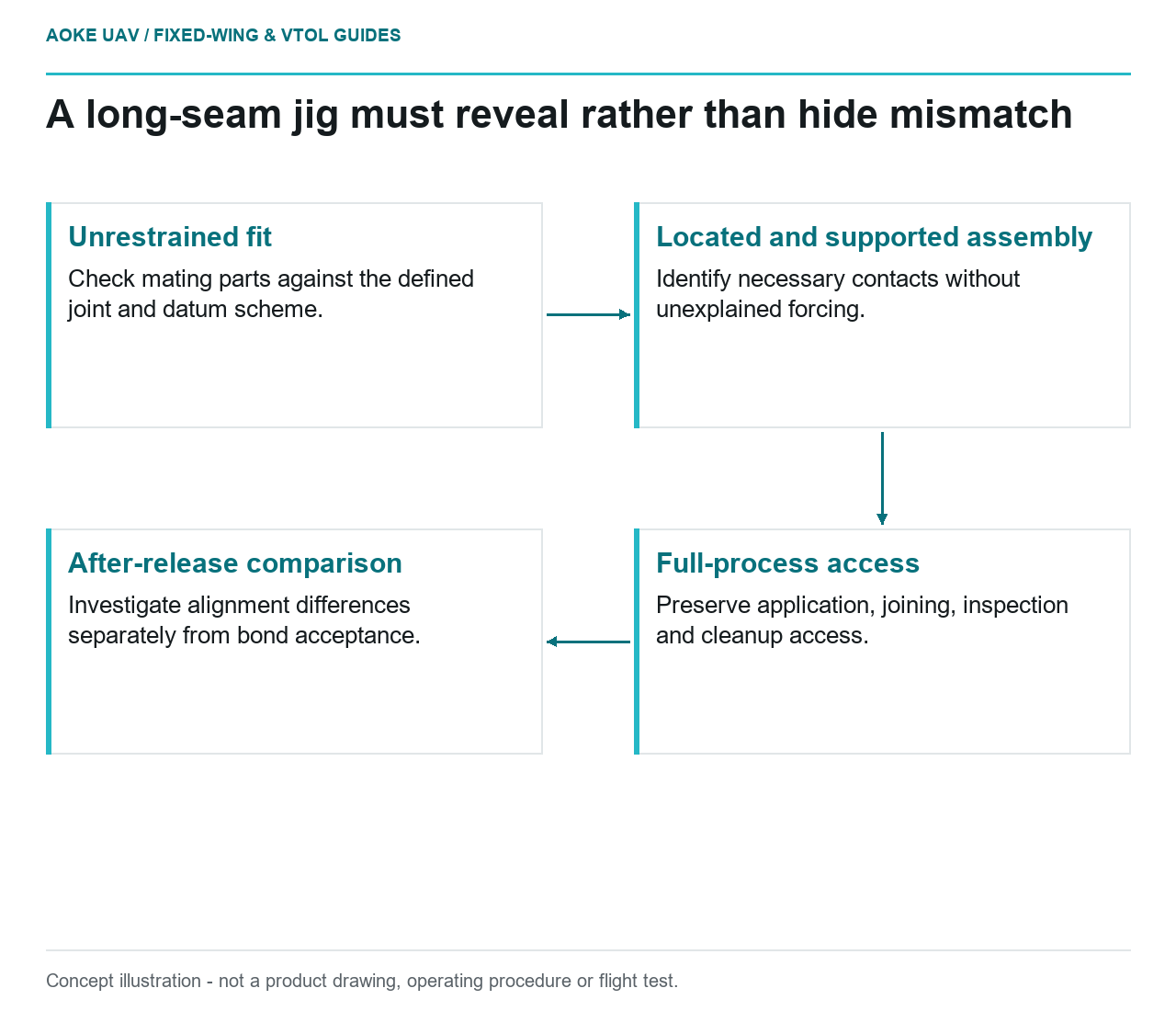
- Unrestrained fit: Check mating parts against the defined joint and datum scheme.
- Located and supported assembly: Identify necessary contacts without unexplained forcing.
- Full-process access: Preserve application, joining, inspection and cleanup access.
- After-release comparison: Investigate alignment differences separately from bond acceptance.
A bonding fixture is not a bond specification. In a hypothetical manufacturing study, a large fixed-wing survey wing has a long structural seam whose joint geometry and adhesive process are already defined by responsible engineering documents. Printed jig modules are proposed to hold the assembly. This article concerns what those modules must locate, support and leave accessible; it does not redesign the joint or prescribe adhesive thickness, pressure or cure settings.
Hold the intended geometry without hiding mismatch
FAA composite-structure guidance treats mating-part tolerances, clamp-up, bondline control and cure management as parts of a controlled bonding process. It is certificated-aircraft guidance, not approval of this UAV wing. [3]
For our fixed-wing seam, draw the datum scheme before designing individual printed nests. Specify what each support locates and which movements it leaves free. Review the as-received fit before clamping. If the halves only meet after unexplained forcing, report the discrepancy instead of using the jig to erase the evidence.
Along a multi-meter wing, identify where operators will verify seating and where the joint becomes obscured. Do not assume that a fixture touching many locations automatically controls the intended shape. Our proposed review would ask which contacts are necessary, which are redundant and how an incorrectly seated section would be detected before adhesive application.
Preserve access throughout the process
Walk through the approved assembly procedure with representative parts and the proposed jig. Check access for preparation, application, joining, inspection and cleanup at each stage. A tool can provide convenient loading access while blocking the exact region that must be observed after the parts come together.
Separate the fixture’s release strategy from bond-surface preparation. The FAA document explicitly includes surface handling and contamination control in its bonding discussion. [3] In this scenario, any proposed release material near the seam would therefore require a compatibility and contamination review under the applicable process. Do not infer acceptability from its use on a different mold.
Our suggested dry run would use a nonflight representative assembly and record inaccessible locations before any adhesive trial. Include the actual intended clamps, temporary supports and inspection equipment. An unobstructed CAD section is not a demonstration that an operator can perform the specified task when the complete fixture is present.
Assess the jig under the intended exposure
Stratasys discusses thermal expansion and material-specific composite tooling behavior. Those examples do not supply settings or universal stability for an arbitrary printed bonding jig. [1] Obtain the actual bond process exposure from its governing documents, then assess the entire proposed tooling system against it.
For this fixed-wing scenario, the assessment would include printed modules, their supports, fasteners and interfaces to the wing. State what geometry must be maintained during the relevant process stages and how a representative demonstration will evaluate it. A room-temperature location check answers a narrower question than a complete process trial.
Keep temporary restraint decisions explicit. Where a process includes heating or cooling, identify which interfaces permit intended movement and which establish datums. This is a review question, not a recommendation to add sliding joints without analysis. If the team cannot define the intended restraint behavior, the fixture design is not ready to be accepted on appearance alone.
Keep fixture and bond records distinct
Our proposed tooling record would identify jig revision, datum measurements, support arrangement and any changes after a trial. The bond record would separately identify the applicable materials, process revision, in-process checks and required acceptance evidence. A passing tool inspection cannot stand in for bond-process qualification or a required assembly inspection.
Before further use, resolve whether measured alignment remains acceptable after the assembly is released from the jig. Investigate discrepancies through the responsible engineering process rather than silently adjusting supports for the next wing. The outcome sought here is a traceable ground-tool decision. It is not an GAUTEN manufacturing claim, proof of structural joint strength or authorization to fly a fixed-wing aircraft built in the proposed fixture.
Related reading
- Bondline Thickness Control Without a Universal Recipe
- Bond Preparation Records for Composite Airframes