Control role in adjustment
In a hypothetical large-area civil survey, a fixed-wing UAV will acquire a mapping block, but most proposed ground control lies beside the launch access road. USGS explains that ground control constrains image self-calibration and that its spatial positioning and accuracy influence UAS data quality. [1] The review question is therefore not simply how many targets can be placed. It is what the proposed observations actually constrain across the intended product.
Give each proposed ground point a defined role before processing. For this scenario, distinguish observations used in adjustment from observations reserved for independent assessment. Record the reference frame, survey method and uncertainty evidence with the point identifier. An attractive target layout is not enough if the coordinates themselves cannot support the measurement requirement. Likewise, precise coordinates are not useful control observations unless the relevant point can be identified in the imagery used for the adjustment.
Spatial distribution and elevation range
USGS discusses distributing control and tie points in both horizontal and vertical dimensions; it also notes that calibration and acquisition geometry are interdependent. [1] In our fixed-wing block, plot the control against the requested data boundary, proposed strips and terrain zones. The objective is to expose the difference between an accessible cluster and a network that plausibly supports the whole measurement area. No universal target count or spacing is established by this discussion.
Ask the survey specialist to explain where the adjustment relies most strongly on observations outside the accessible cluster. Include the distant edge and relevant elevation differences in that explanation. If a configuration relies on other positioning evidence, describe what that evidence contributes and how the final product will still be assessed. Do not convert the presence of a precise navigation system into an unexamined assertion that the control distribution no longer matters.
Target visibility and image support
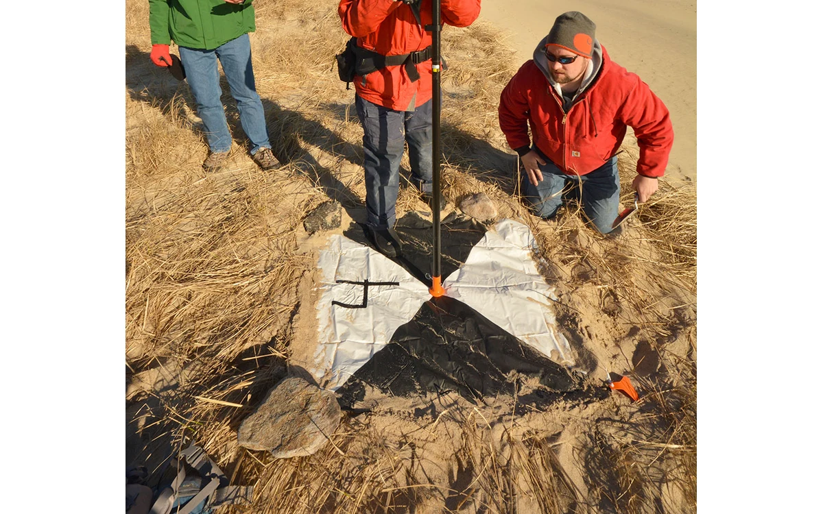
For this hypothetical large industrial fixed-wing installation, connect target design to the actual image plan. Check that the intended target reference point can be identified at the proposed local sampling, viewing geometry and illumination. Identify which accepted images observe it and whether those observations represent useful positions within the block. Keep a target’s surveyed location distinct from a merely visible object nearby; the point being measured must be unambiguous to the processing reviewer.
Document this check without inventing target dimensions. The appropriate design belongs to the project’s survey method and actual camera configuration, not an arbitrary large-aircraft rule. If a point is absent, obscured or ambiguously marked in the acquired images, preserve its status instead of silently replacing its observation. Ask how the resulting change affects the adjustment rationale and whether it creates an area requiring additional evidence before the map can be accepted.
Documenting inaccessible areas and limitations
Use an access-limitation map rather than hiding the gaps in a point total. In the fictional project, distinguish locations that could not be surveyed from locations that were surveyed but could not be observed usefully in the imagery. Keep proposed remedies traceable: additional access, revised acquisition geometry, a narrower deliverable or an explicitly qualified assessment. The flight team must separately review any route change against actual aircraft and operational constraints.
USGS notes that checkpoint quality determines how well a dataset can be validated. [1] Close the control review by naming what independent evidence will test the parts of this large fixed-wing block that matter to the client. Preserve the final control list, its adjustment role and any exclusions with the delivered product version. That is a defensible handover structure; it is not an assertion that the hypothetical road-side control cluster achieved acceptable accuracy elsewhere.
A proposed control register could contain the point identifier, surveyed reference point, coordinate-system definition, uncertainty record, image observations and adjustment status. Include a reason where an intended point was not used. Join this register to the proposed flight strips so the reviewer can follow a control observation from its physical target to its role in the block. That trace is more informative than reporting a count without explaining where the points act.
Related reading
Sources
Visual summary
Concept illustration
Read diagram notes
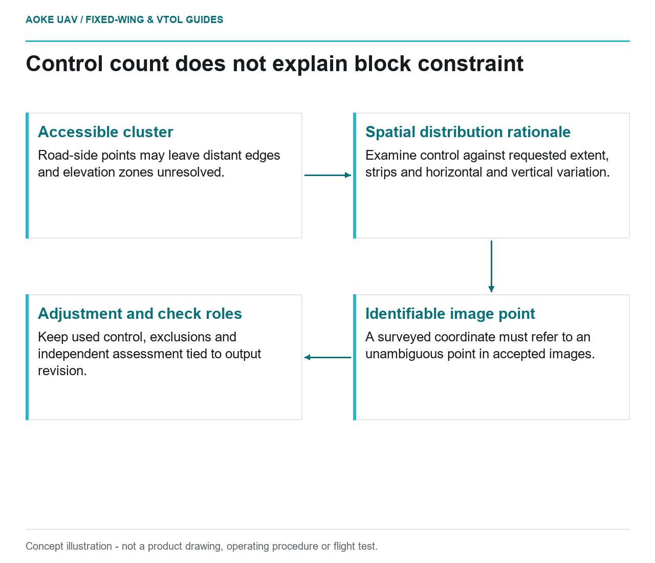
- Accessible cluster: Road-side points may leave distant edges and elevation zones unresolved.
- Spatial distribution rationale: Examine control against requested extent, strips and horizontal and vertical variation.
- Identifiable image point: A surveyed coordinate must refer to an unambiguous point in accepted images.
- Adjustment and check roles: Keep used control, exclusions and independent assessment tied to output revision.